Improving Performance of Progressive Dies
Progressive die stamping is a cost-effective and safe method of producing components. Careful design and construction of dies will ensure optimum performance.
A progressive die performs a series of fundamental sheet metal operations at two or more stations in the die during each press stroke. These simultaneous operations produce a part from a strip of material that moves through the die. Each working station performs one or more die operations, but the strip must move from the first station through each succeeding station to produce a complete part. Carriers, consisting of one or more strips of material left between the parts, provide movement of the parts from one die station to the next. These carrier strips are separated from the parts in the last die station.
There are six elements that should be addressed when designing and building a progressive die to maximize its performance: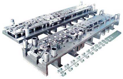
Interpreting the part print
Starting material into the die
Part lifters and part feeding
Flexible part carriers
Upper pressure pads
Drawn shells.
Interpreting the Part Print
The first step in the proper design of a progressive die is to correctly analyze the part print. The tool designer must interpret the print to determine the function of the part by looking for such things as the type of material, critical surfaces, hole size and location, burr location, grain direction requirements, surface finish and other factors.
The die designer must understand the part well, particularly if it has irregular shapes and contours. However, modern computer-drawn prints make this more difficult because computer-drawn part data can be downloaded directly to the die-design computer. As a result, the designer may not become thoroughly familiar with important part features.
Also, many computer-drawn parts are more difficult to understand, because often, only one surface is shown and it may be the inside or outside surface. Computer drawings often show all lines, including hidden features, as solid lines instead of dotted lines. This leads to interpretation errors, which in turn leads to errors in the building of the die.
To better understand complex part shapes, it is helpful to build a "sight" model of the part using sheet wax, rubber skins or wood models. Dimensional accuracy is not critical for these models, as they are used primarily to visualize the part. Rubber skins and sheet wax also can be used to develop preform shapes and to develop the best positions for the part as it passes through each die operation in the progressive die.
Starting Material in the Die
Care must be taken to ensure that the strip is started correctly into the die. Improper location of the lead end of the strip will do more damage to the die in the first 10 strokes of the press than the next 100,000 strokes.
"Lead-in" gauges must have large leads and a ledge to support the lead end of the coil strip when it is inserted into the die. Large leads on the gauges are important so that the die setup person does not have to reach into the die, as well as for minimizing the time required to start a new strip into the die. Also, one gauge should be adjustable to compensate for variation in strip width.
The position of the lead edge of the strip is critical for the first press stroke, and must be determined for every die station to ensure that piercing punches do not cut partial holes in the lead edge. This could cause punch deflection or result in a partial cut with trimming punches, which can result in an unbalanced side load as the strip passes through the die. Any of these conditions can result in a shift of the punch-to-die relationship that may cause shearing of the punches.
Improper location of the lead edge of the strip also can result in an unbalanced forming or flanging condition that can shift the upper die in relation to the lower die. Heels should be required to absorb this side load, particularly when forming thick materials.
A pitch notch and pitch stop can provide a physical point to locate and control the lead edge of the strip. Brass tags or marker grooves also can provide a visual location, but these are not as accurate or as effective as a pitch notch stop. The press can be prevented from operating with either a short feed or over feed by mounting the pitch stop on a pivot and monitoring it with a limit switch
Part Lifters and Part Feeding
Progressive dies often require the strip to be lifted from the normal die work level to the feed level before strip feeding takes place. This can vary from a small amount--to clear trim and punching burrs--to several inches to allow part shapes to clear the die.
Normally, all lifters should rise to the same height so that the strip is supported in a level plane during forward feed. The strip must not sag between lifters; otherwise parts will be pulled out of their correct station location spacing. Bar lifters provide good support and are better than spring pins or round lifters notched on one side of the strip.
Often, a good bar lifter system allows higher press speeds because feed problems are eliminated. Although the initial cost is more than round lifters, performance is better and setup time is reduced.
As the strip is started into the lead-in gauges, the strip should be able to feed automatically through all the following die stations without requiring manual alignment in each set of gauges and lifters. The strip also must be balanced on the lifters so that it does not fall to one side during feed. A retainer cap can be mounted on the top of the outside bar lifters. This produces a groove that captures the strip during feed and prevents strip buckling.
Gauging and lifter conditions can be simulated during die design by cutting a piece of transparent paper to the width of the strip. The lead edge of the paper is placed over the plan view of the die design at the location the strip will be for the first press stroke. Then the paper is marked with all of the operations that will be performed at the first die station--for example, notching and punching. The paper strip then is moved to the second station on the drawing and the operations for both the first and second stations are marked. This process is repeated through all the die stations to illustrate what the real part strip will look like when it is started into the die and helps determine the adequacy of gauges and lifters.
Flexible Part Carriers
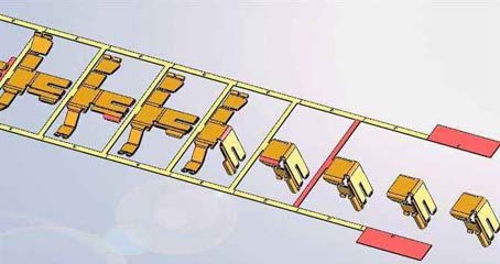
To transport the strip from one station to the next in a progressive die, some material must be left between the parts on the strip. This carrier material may be solid across the width of the strip, or may be one or more narrow ribbons of material, see part carriers sidebar.
Many parts require the edge of the blank to flow inward during flanging, forming or drawing operations. This may require the carrier to move sideways or flex vertically, or both, during the die operation. A flexible loop must be provided in the carrier to allow flexing and movement of the blank without pulling the adjacent parts out of position.
Another concern is the vertical "breathing" of parts in die stations during the closing and opening of the die in the press stroke. For example, vertical breathing takes place between the draw stations of parts requiring more than one draw to complete the part. Vertical breathing also occurs when a flange is formed "up" in a progressive die station that is adjacent to stations that use upper pressure pads to hold the adjacent parts down.
It is important to consider the flexing of the carrier during the upstroke of the press as well as during the downstroke because the action may be different. This can be simulated in the design stage by making an outline of the cross-section of the part, the pressure pads and the stationary-mounted steels on separate sheets of paper and then placing these sheets on top of each other in layers over the die section views. These sheets then are moved down in relation to each other to simulate how the upper die would close during the press downstroke. This will show the relative position of the part as the die closes and during the reverse action as the die ram opens.
A common feature in all progressive stamping dies is the material that transports the parts from station-to-station as it passes through the die. This material is known by various terms, such as carrier, web, strip, tie, attachment, etc. In this instance, we will use the term carrier, of which there are five basic styles:
Solid carrier--All required work can be accomplished on the part without preliminary trimming. The part is cut off or blanked in the final operation.
Center carrier--The periphery of the part is trimmed; leaving only a narrow tie near the middle of the part. This permits work to be performed all around the part. A wide center carrier permits trimming only at the sides of the part.
Lance and carry at the center--The strip is lanced between parts, leaving a narrow area near the center to carry the parts.
This eliminates scrap material between parts.
Outside carriers--The carriers are attached to the sides of the part so that work can be done to the center of the part.
One side carrier--The part is carried all the way or part of the way through the die with the carrier on one side only. This permits work on three sides of the part.
The type or shape of the carrier will vary depending on what the part requires as it progresses from station to station in the die. The stock width may be left solid if no part material motion is required during die closure or it can be notched to create one, two or even three carriers between the parts.
The carriers can be straight, form a zig-zag pattern or have loops between the parts depending on where attachment points to the part are available or to accommodate whatever clearance may be required by the die tooling. As the part is formed, flanged or drawn into a shell, the carrier may have to move sideways or up and down as the die closes and opens.
When die operations cause the carrier to move, it usually will be required to flex or stretch. Regardless of carrier flexing, their key function is to move the parts close enough to the next station so that pilots, gauges and locators can put the parts into their precise location as the die closes.
If the carrier acquires a permanent stretch, the parts may progress too far to fit on the next station, or in the case that the die has two carriers, one carrier may develop permanent stretch with no stretch in the other carrier. This will create edge camber in the strip, causing it to veer to one side. This results in poor part location.
A stretched carrier can be shortened to its correct length by putting a dimple in the carrier. If a center carrier or one-sided carrier develops camber, the strip can be straightened by dimpling or scoring one side of the carrier. Construct the dimple and scoring punches so that they are easily adjusted sideways for position and vertically for depth.
Edge camber of the material as it is delivered from the coil can cause the strip to bind in the running gauges that guide the material during the feed cycle. This binding may cause the carriers to buckle, which results in short feeds. It often helps to relieve the guide edge of the gauges in between stations and have tighter gauge control at the work station.
Another option is to eliminate camber by trimming both sides of the material in the beginning of the die. By adding stops at the end of these trim notches they can be used as pitch control notches to prevent progression overfeed.
Optimum Carrier Profile
The optimum carrier profile is affected by some of the following conditions:
Space available between parts: Try to keep the carriers within the stock width and pitch required for the blank. If this is not possible then the designer must add to the width and/or the progression of the material to provide adequate carrier room.
Attachment points to the part: If two carriers are used, try to keep the profile and length of the carriers somewhat the same so that any effect of carrier flexing is close to being balanced.
Clearance for punch and die blocks: Punch blocks that extend below the stock or die blocks that extend above the stock when the die closes will require clearance in relation to the parts and the carriers. If a loop of the carrier interferes with blocks it may be possible to form the loop vertical to provide clearance.
Thickness of the material: Large parts with thin material may require stiffener beads to add strength to the carrier for stock feeding. Another stiffening and strip guiding method is to lance and flange the edge of the stock, which also can be used as a progression notch.
The total of the strip: Heavy parts in long dies require more force to push the strip through the die. However, the weight is usually thick material, and thick material is stiffer than thin material. As a rule of thumb, flexible carriers for
materials of 0.020 in. to 0.060 in. are about 3/16 in. to 5/16 in. wide. For stock thicknesses above and below this thickness range, carrier
width is a "best judgment call."
Depending on all the die factors involved, under normal conditions the carriers should be a consistent width for their full length, but especially in the area of flexing. Since nearly every stock feeder pushes material through the die rather than pull the material, the carrier must be strong enough to push the parts all the way through the die.
A detection switch actuated by a complete feed of the strip at the exit of the die can detect buckling. If action of the die during closure or opening of the press requires the carriers to flex, design the carrier with loops that are long enough to flex without breaking, but still strong enough to feed all the parts to their full progression. If two flex carriers are not strong enough to feed the strip, consider three carriers.
Try to make the radii in flex loops as large as practical. Sharp corners or small radii will concentrate stress of flexing, making it the first point to fracture during flexing of the carrier. Also avoid any steps or nicks in the edges of the carrier.
Upper Pressure Pads
Because of size or function, many progressive dies require two or more pressure pads in the upper die. Each may require a different travel distance to perform the work in the individual die station, such as trimming or forming or drawing.
However, the upper pressure pads often are used to push the material lifters down by pressing against the strip, which pushes the lifters down. In this situation, all of the pressure pads that push material lifters down should have the same travel distance. If the upper pressure pads travel different distances, the strip will not be pushed down evenly. This can pull adjacent parts out of the progression, making it difficult to locate the parts in their proper station position after the feed cycle.
If the part requires a flange to be formed up, the part carrier must have a flex loop to allow for vertical breathing of the part or provide a pressurized punch/pad with the same travel as the other pressure pads. The force required by the pressurized punch/pad has to be adequate to form the flanges up during the downstroke while the punch/ pad is in the extended position. This keeps the strip from breathing vertically as it is pushed down from the feed level to the normal work level.
When the strip reaches the work level, the pressurized punch/pad stops its downward motion while the upper die continues down for punching, trimming, down flanging and other operations. Springs or nitrogen cylinders can be used for pressure in these pressurized punch/ pad stations, but they must have enough preload force to form the flanges up and to collapse the lower gripper pad before the upper punch/ pad recedes.
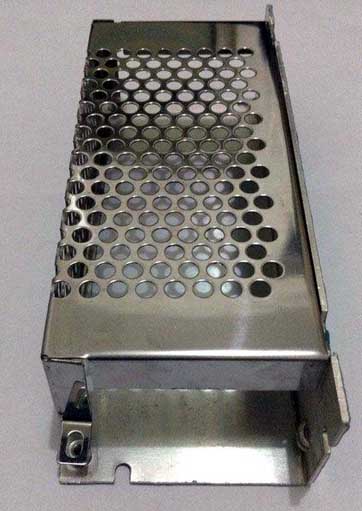
Drawn Shells
Drawn shells are produced when strip material is changed from a flat plane to a cylindrical shape. During the draw operation, the "diameter" of the blank is reduced to the "circumference" of the shell. As the circumference is being reduced during the flow of material inward, the outer portion of the material goes into side or edge compression.
When this compression becomes too great for the material to stay flat, it begins to fold or wrinkle. To prevent this, the material is allowed to flow in a controlled gap between a draw ring and a pressure pad. The two main causes of failure in drawing a shell are to exceed the percentage that the blank (or shell) is reduced in diameter and an improper draw ring radius.
There is a limit to how far inward metal will flow when drawing from the blank diameter to the first draw diameter and from a drawn shell diameter to a smaller shell diameter. This is expressed as a percentage of draw reduction. The maximum percentage of reduction is limited by the flow of material inward that causes the metal to go into compression, which in turn causes a resistance to flow. Too much resistance will cause fracture near the cap of the shell, which is the weakest area in tension.
The percentage of reduction varies with the metal thickness. For example, for a deep drawing steel blank, the percentage of reduction to the first draw shell diameter varies from 32 percent for 0.015-in. thick material to 48 percent for 0.125-in. thick material.
There is a minimum and maximum draw radius on the draw ring that will control the flow of material. For deep drawing steel parts, the correct radius varies from 5/32-in. minimum to 1/4 in. maximum for 0.015-in. stock, and 11/32-in. minimum to 15/32 in. maximum for 0.125-in. stock.
If the radius is too small, the metal will not flow well, which increases the resistance to flow, causing excessive thinning or fractures near the cap of the cup. If the radius is too large, the metal will wrinkle after it leaves the point of pinch between the draw ring and the pressure pad, and before it is formed into the vertical wall of the cup.
The normal tendency is to make the radius too small because "it's easy to make the radius larger during die tryout and it's difficult to make a smaller radius." The result is that needless stress is put on the cup, which results in excessive thinning or fracturing. Many times the problem of an improper percentage of reduction or improper draw radius in the first draw station will not show up in the first draw station, but in a later redraw station, with the result that considerable time is spent trying to fix the wrong station.
A progressive die performs a series of fundamental sheet metal operations at two or more stations in the die during each press stroke. These simultaneous operations produce a part from a strip of material that moves through the die. Each working station performs one or more die operations, but the strip must move from the first station through each succeeding station to produce a complete part. Carriers, consisting of one or more strips of material left between the parts, provide movement of the parts from one die station to the next. These carrier strips are separated from the parts in the last die station.
There are six elements that should be addressed when designing and building a progressive die to maximize its performance:
Interpreting the part print
Starting material into the die
Part lifters and part feeding
Flexible part carriers
Upper pressure pads
Drawn shells.
Interpreting the Part Print
The first step in the proper design of a progressive die is to correctly analyze the part print. The tool designer must interpret the print to determine the function of the part by looking for such things as the type of material, critical surfaces, hole size and location, burr location, grain direction requirements, surface finish and other factors.
The die designer must understand the part well, particularly if it has irregular shapes and contours. However, modern computer-drawn prints make this more difficult because computer-drawn part data can be downloaded directly to the die-design computer. As a result, the designer may not become thoroughly familiar with important part features.
Also, many computer-drawn parts are more difficult to understand, because often, only one surface is shown and it may be the inside or outside surface. Computer drawings often show all lines, including hidden features, as solid lines instead of dotted lines. This leads to interpretation errors, which in turn leads to errors in the building of the die.
To better understand complex part shapes, it is helpful to build a "sight" model of the part using sheet wax, rubber skins or wood models. Dimensional accuracy is not critical for these models, as they are used primarily to visualize the part. Rubber skins and sheet wax also can be used to develop preform shapes and to develop the best positions for the part as it passes through each die operation in the progressive die.
Starting Material in the Die
Care must be taken to ensure that the strip is started correctly into the die. Improper location of the lead end of the strip will do more damage to the die in the first 10 strokes of the press than the next 100,000 strokes.
"Lead-in" gauges must have large leads and a ledge to support the lead end of the coil strip when it is inserted into the die. Large leads on the gauges are important so that the die setup person does not have to reach into the die, as well as for minimizing the time required to start a new strip into the die. Also, one gauge should be adjustable to compensate for variation in strip width.
The position of the lead edge of the strip is critical for the first press stroke, and must be determined for every die station to ensure that piercing punches do not cut partial holes in the lead edge. This could cause punch deflection or result in a partial cut with trimming punches, which can result in an unbalanced side load as the strip passes through the die. Any of these conditions can result in a shift of the punch-to-die relationship that may cause shearing of the punches.
Improper location of the lead edge of the strip also can result in an unbalanced forming or flanging condition that can shift the upper die in relation to the lower die. Heels should be required to absorb this side load, particularly when forming thick materials.
A pitch notch and pitch stop can provide a physical point to locate and control the lead edge of the strip. Brass tags or marker grooves also can provide a visual location, but these are not as accurate or as effective as a pitch notch stop. The press can be prevented from operating with either a short feed or over feed by mounting the pitch stop on a pivot and monitoring it with a limit switch
Part Lifters and Part Feeding
Progressive dies often require the strip to be lifted from the normal die work level to the feed level before strip feeding takes place. This can vary from a small amount--to clear trim and punching burrs--to several inches to allow part shapes to clear the die.
Normally, all lifters should rise to the same height so that the strip is supported in a level plane during forward feed. The strip must not sag between lifters; otherwise parts will be pulled out of their correct station location spacing. Bar lifters provide good support and are better than spring pins or round lifters notched on one side of the strip.
Often, a good bar lifter system allows higher press speeds because feed problems are eliminated. Although the initial cost is more than round lifters, performance is better and setup time is reduced.
As the strip is started into the lead-in gauges, the strip should be able to feed automatically through all the following die stations without requiring manual alignment in each set of gauges and lifters. The strip also must be balanced on the lifters so that it does not fall to one side during feed. A retainer cap can be mounted on the top of the outside bar lifters. This produces a groove that captures the strip during feed and prevents strip buckling.
Gauging and lifter conditions can be simulated during die design by cutting a piece of transparent paper to the width of the strip. The lead edge of the paper is placed over the plan view of the die design at the location the strip will be for the first press stroke. Then the paper is marked with all of the operations that will be performed at the first die station--for example, notching and punching. The paper strip then is moved to the second station on the drawing and the operations for both the first and second stations are marked. This process is repeated through all the die stations to illustrate what the real part strip will look like when it is started into the die and helps determine the adequacy of gauges and lifters.
Flexible Part Carriers
To transport the strip from one station to the next in a progressive die, some material must be left between the parts on the strip. This carrier material may be solid across the width of the strip, or may be one or more narrow ribbons of material, see part carriers sidebar.
Many parts require the edge of the blank to flow inward during flanging, forming or drawing operations. This may require the carrier to move sideways or flex vertically, or both, during the die operation. A flexible loop must be provided in the carrier to allow flexing and movement of the blank without pulling the adjacent parts out of position.
Another concern is the vertical "breathing" of parts in die stations during the closing and opening of the die in the press stroke. For example, vertical breathing takes place between the draw stations of parts requiring more than one draw to complete the part. Vertical breathing also occurs when a flange is formed "up" in a progressive die station that is adjacent to stations that use upper pressure pads to hold the adjacent parts down.
It is important to consider the flexing of the carrier during the upstroke of the press as well as during the downstroke because the action may be different. This can be simulated in the design stage by making an outline of the cross-section of the part, the pressure pads and the stationary-mounted steels on separate sheets of paper and then placing these sheets on top of each other in layers over the die section views. These sheets then are moved down in relation to each other to simulate how the upper die would close during the press downstroke. This will show the relative position of the part as the die closes and during the reverse action as the die ram opens.
A common feature in all progressive stamping dies is the material that transports the parts from station-to-station as it passes through the die. This material is known by various terms, such as carrier, web, strip, tie, attachment, etc. In this instance, we will use the term carrier, of which there are five basic styles:
Solid carrier--All required work can be accomplished on the part without preliminary trimming. The part is cut off or blanked in the final operation.
Center carrier--The periphery of the part is trimmed; leaving only a narrow tie near the middle of the part. This permits work to be performed all around the part. A wide center carrier permits trimming only at the sides of the part.
Lance and carry at the center--The strip is lanced between parts, leaving a narrow area near the center to carry the parts.
This eliminates scrap material between parts.
Outside carriers--The carriers are attached to the sides of the part so that work can be done to the center of the part.
One side carrier--The part is carried all the way or part of the way through the die with the carrier on one side only. This permits work on three sides of the part.
The type or shape of the carrier will vary depending on what the part requires as it progresses from station to station in the die. The stock width may be left solid if no part material motion is required during die closure or it can be notched to create one, two or even three carriers between the parts.
The carriers can be straight, form a zig-zag pattern or have loops between the parts depending on where attachment points to the part are available or to accommodate whatever clearance may be required by the die tooling. As the part is formed, flanged or drawn into a shell, the carrier may have to move sideways or up and down as the die closes and opens.
When die operations cause the carrier to move, it usually will be required to flex or stretch. Regardless of carrier flexing, their key function is to move the parts close enough to the next station so that pilots, gauges and locators can put the parts into their precise location as the die closes.
If the carrier acquires a permanent stretch, the parts may progress too far to fit on the next station, or in the case that the die has two carriers, one carrier may develop permanent stretch with no stretch in the other carrier. This will create edge camber in the strip, causing it to veer to one side. This results in poor part location.
A stretched carrier can be shortened to its correct length by putting a dimple in the carrier. If a center carrier or one-sided carrier develops camber, the strip can be straightened by dimpling or scoring one side of the carrier. Construct the dimple and scoring punches so that they are easily adjusted sideways for position and vertically for depth.
Edge camber of the material as it is delivered from the coil can cause the strip to bind in the running gauges that guide the material during the feed cycle. This binding may cause the carriers to buckle, which results in short feeds. It often helps to relieve the guide edge of the gauges in between stations and have tighter gauge control at the work station.
Another option is to eliminate camber by trimming both sides of the material in the beginning of the die. By adding stops at the end of these trim notches they can be used as pitch control notches to prevent progression overfeed.
Optimum Carrier Profile
The optimum carrier profile is affected by some of the following conditions:
Space available between parts: Try to keep the carriers within the stock width and pitch required for the blank. If this is not possible then the designer must add to the width and/or the progression of the material to provide adequate carrier room.
Attachment points to the part: If two carriers are used, try to keep the profile and length of the carriers somewhat the same so that any effect of carrier flexing is close to being balanced.
Clearance for punch and die blocks: Punch blocks that extend below the stock or die blocks that extend above the stock when the die closes will require clearance in relation to the parts and the carriers. If a loop of the carrier interferes with blocks it may be possible to form the loop vertical to provide clearance.
Thickness of the material: Large parts with thin material may require stiffener beads to add strength to the carrier for stock feeding. Another stiffening and strip guiding method is to lance and flange the edge of the stock, which also can be used as a progression notch.
The total of the strip: Heavy parts in long dies require more force to push the strip through the die. However, the weight is usually thick material, and thick material is stiffer than thin material. As a rule of thumb, flexible carriers for
materials of 0.020 in. to 0.060 in. are about 3/16 in. to 5/16 in. wide. For stock thicknesses above and below this thickness range, carrier
width is a "best judgment call."
Depending on all the die factors involved, under normal conditions the carriers should be a consistent width for their full length, but especially in the area of flexing. Since nearly every stock feeder pushes material through the die rather than pull the material, the carrier must be strong enough to push the parts all the way through the die.
A detection switch actuated by a complete feed of the strip at the exit of the die can detect buckling. If action of the die during closure or opening of the press requires the carriers to flex, design the carrier with loops that are long enough to flex without breaking, but still strong enough to feed all the parts to their full progression. If two flex carriers are not strong enough to feed the strip, consider three carriers.
Try to make the radii in flex loops as large as practical. Sharp corners or small radii will concentrate stress of flexing, making it the first point to fracture during flexing of the carrier. Also avoid any steps or nicks in the edges of the carrier.
Upper Pressure Pads
Because of size or function, many progressive dies require two or more pressure pads in the upper die. Each may require a different travel distance to perform the work in the individual die station, such as trimming or forming or drawing.
However, the upper pressure pads often are used to push the material lifters down by pressing against the strip, which pushes the lifters down. In this situation, all of the pressure pads that push material lifters down should have the same travel distance. If the upper pressure pads travel different distances, the strip will not be pushed down evenly. This can pull adjacent parts out of the progression, making it difficult to locate the parts in their proper station position after the feed cycle.
If the part requires a flange to be formed up, the part carrier must have a flex loop to allow for vertical breathing of the part or provide a pressurized punch/pad with the same travel as the other pressure pads. The force required by the pressurized punch/pad has to be adequate to form the flanges up during the downstroke while the punch/ pad is in the extended position. This keeps the strip from breathing vertically as it is pushed down from the feed level to the normal work level.
When the strip reaches the work level, the pressurized punch/pad stops its downward motion while the upper die continues down for punching, trimming, down flanging and other operations. Springs or nitrogen cylinders can be used for pressure in these pressurized punch/ pad stations, but they must have enough preload force to form the flanges up and to collapse the lower gripper pad before the upper punch/ pad recedes.
Drawn Shells
Drawn shells are produced when strip material is changed from a flat plane to a cylindrical shape. During the draw operation, the "diameter" of the blank is reduced to the "circumference" of the shell. As the circumference is being reduced during the flow of material inward, the outer portion of the material goes into side or edge compression.
When this compression becomes too great for the material to stay flat, it begins to fold or wrinkle. To prevent this, the material is allowed to flow in a controlled gap between a draw ring and a pressure pad. The two main causes of failure in drawing a shell are to exceed the percentage that the blank (or shell) is reduced in diameter and an improper draw ring radius.
There is a limit to how far inward metal will flow when drawing from the blank diameter to the first draw diameter and from a drawn shell diameter to a smaller shell diameter. This is expressed as a percentage of draw reduction. The maximum percentage of reduction is limited by the flow of material inward that causes the metal to go into compression, which in turn causes a resistance to flow. Too much resistance will cause fracture near the cap of the shell, which is the weakest area in tension.
The percentage of reduction varies with the metal thickness. For example, for a deep drawing steel blank, the percentage of reduction to the first draw shell diameter varies from 32 percent for 0.015-in. thick material to 48 percent for 0.125-in. thick material.
There is a minimum and maximum draw radius on the draw ring that will control the flow of material. For deep drawing steel parts, the correct radius varies from 5/32-in. minimum to 1/4 in. maximum for 0.015-in. stock, and 11/32-in. minimum to 15/32 in. maximum for 0.125-in. stock.
If the radius is too small, the metal will not flow well, which increases the resistance to flow, causing excessive thinning or fractures near the cap of the cup. If the radius is too large, the metal will wrinkle after it leaves the point of pinch between the draw ring and the pressure pad, and before it is formed into the vertical wall of the cup.
The normal tendency is to make the radius too small because "it's easy to make the radius larger during die tryout and it's difficult to make a smaller radius." The result is that needless stress is put on the cup, which results in excessive thinning or fracturing. Many times the problem of an improper percentage of reduction or improper draw radius in the first draw station will not show up in the first draw station, but in a later redraw station, with the result that considerable time is spent trying to fix the wrong station.


