Stamping Die Supplier


- PRODUCT DETAIL
Product Name
Stamping die is a kind of special process equipment that processes material (metal or non-metal) into parts (or semi-finished products) in cold stamping process. It is called cold stamping die (commonly known as cold die).
Stamping is a pressure processing method that uses a mold mounted on a press to apply pressure to a material at room temperature to cause separation or plastic deformation, thereby obtaining a desired part.
Design
Metal mold design should pay attention to the spacing between the modules, parts processing accuracy, accuracy of assembly, accuracy of fit, and interference issues, in order to achieve continuous mold automation mass production purposes.
The overall structure of the stamping die can be divided into two parts
(1). Common parts
(2). Parts that change according to the product.
Drawing design
(1) Digitization of drawings - the conversion of three-dimensional products and mold models into two-dimensional drawings for routine machining;
(2) The digital design of the mold - according to the product model and design intent, establish a relevant three-dimensional solid model of the mold;
(3) Digital analysis and simulation of molds: According to the forming process conditions of the molds, structural analysis, thermal analysis, fatigue analysis and mold movement analysis of the mold parts are performed;
(4) product forming process simulation - injection molding, stamping molding;
(5) Customized for the company's mold design standard parts and standard design process;
(6) mold production management.
Maintenance
1. Stamping parts burrs
(1) Reasons: A, blade wear; B, clearance is too large after the study knife edge effect is not obvious; C, knife edge collapse; D, the vertical offset or gap unreasonable loose; E, mold up and down dislocation.
(2) mold maintenance:
A, grinding knife; B, control the accuracy of convex and concave mold machining or modify the design gap; C. Adjust the blanking gap, Make sure that the hole in the template is worn out or the precision of the forming part is fixed; D, replace the guide or re-group mode.
2. Mould scraps-jumping produced a bruised
(1) Reason: A, the gap is too large; B. improper pay-off ; C, stamping oil droplets too fast, oil sticky; D, the mold is not demagnetized; E, punch wear, debris attached to the punch; F, the punch is too short, the length of the insert die is insufficient; G. The material is hard and the punching shape is simple.
2) mold maintenance: A, control the accuracy of convex and concave die machining or modify the design gap; B. When it is sent to an appropriate location, trim the material band and clean the mold in time; C, control the amount of oil drip oil, or change the oil to reduce viscosity; D. Demagnetization must be performed after grinding (more attention must be paid to iron material); E, abrasive punch blade; F, adjust the length of the punch edge into the die;
3. Punching scrap material blocking
(1) Reason: A, leakage hole is too small; B. The leakage hole is too large, and the chips are rolling. C. The blade is worn and the raw edges are large; D, stamping oil droplets too fast, oil sticky; E. The surface of the straight edge of the concave die is rough, and the dust is sintered and attached to the edge; F, material is soft;
2) mold maintenance: A, modify the leak hole; B, repair knife edge; C. Control oil drip quantity and change oil type; D, surface treatment, polishing, attention to reduce the surface roughness; change the material, E, modify the blanking gap; F., The punch blade portion end surface repair a slope or curved (note direction), Use a vacuum cleaner to blow air at the Plate hole.
4. Stamping cutting size variation deviation
(1) Reason: A. The convex and concave die edge wear, resulting in burrs; B. Improper design size and clearance, poor processing accuracy; C. Misalignment of punch and die inserts at the lower material position, uneven gaps; D, guide pin wear, lack of pin diameter; E, guide parts wear; F, feeding machine feeding, pressing, loose adjustment improperly; G, improper mold height adjustment; H. The material of the stripping insert is worn, and there is no pressing function; I. The unloading insert is too deep and the punching is too large; J. Variation in mechanical properties of stamping materials; K, punching, punching force on the material traction, causing size variation.
Classification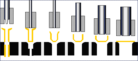
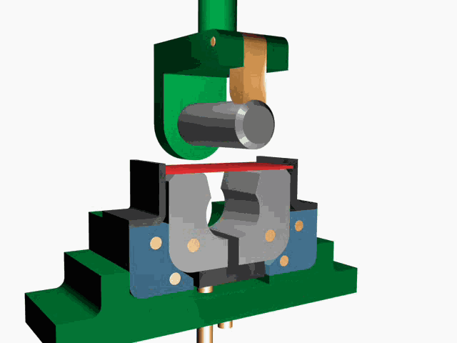
(1) Blanking die: The material is separated along closed or open outlines. Such as blanking die, punching die, cutting die, cutting die, trimming die, cutting die and so on.
(2) Bending mold: The mold of a workpiece having a certain angle and shape is obtained by bending deformation of the plate material along a straight line (bending line).
(3) drawing die: Deep drawing, also called calendering, means using a mold, Punching a certain shape plate blank obtained after punching into various open hollow parts. Or hollow opening diameter is reduced, increasing the height.
(4) Forming mold: It is the mold that the blank or semi-finished product is directly copied and formed according to the shapes of convex and concave molds, and the material itself only produces local plastic deformation. Such as bulging die, shrink die, flaring die, relief forming die, flanging die, and so on.
(5) Single-step die: In one stroke of the press, Only one stamping process is completed.
(6) Compound Die: Only one station, in the press of a stroke, at the same station at the same time to complete two or more stamping process mold.
(7) Continuous stamping die (progressive die): The press uses a strip stamping material during a stamping stroke. In a mold, several stamping steps are completed simultaneously with several different stations. Each stamping of the mold is completed once, and the material belt is moved by a fixed distance until the product is completed.
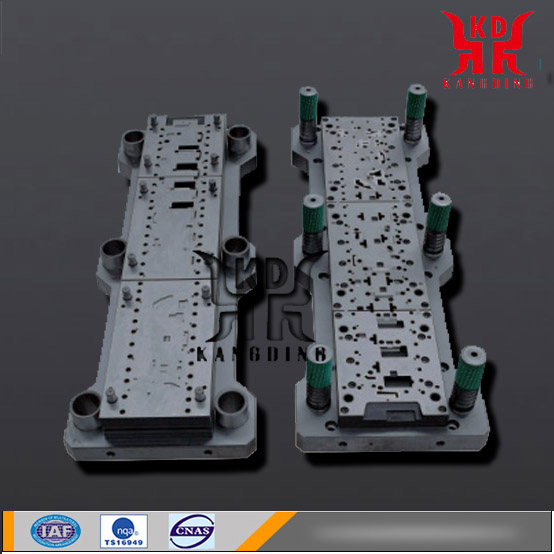
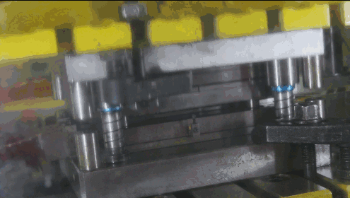
Structure
The products processed by moulds are basically the same in size and appearance. There is no big difference because they can be quickly formed, have high production efficiency, stable product quality, high accuracy, high material utilization, simple operation and low labor intensity. Workers' technical requirements are not high.
Whether the structure of the stamping die is reasonable, whether it is easy to use, whether it can produce a qualified part, and whether the new product developed is successful, the design structure of the die is crucial.
The mold structure is very similar, and the corresponding molds are designed according to different product features and requirements. In general, there are simple and complex molds. But no matter how complicated the structure is, its basic structure is unchanged. Nothing more than a few templates and standard parts.
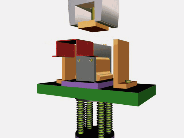
General stamping die structure, the specific template from top to bottom (including code number) is:
Template on the die: Mounting plate, Top block, (UPU), (UBU), (PHU), (PPS), (PSU);
Mold's lower formwork: DIE, LBD, LPD, bottom block, bottom plate;
Less commonly used templates: Upper cover (CVU), hit the board, cope plate, Under the stripper plate, Lower stop baffle, lower plate, male die, master die;
Mold parts: Springs, hex screws, stop screws, wire springs, contour sets, guide posts, guide bushes, Contour gaskets, Dual-use pins, top material pins, etc.;
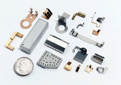
Stamping material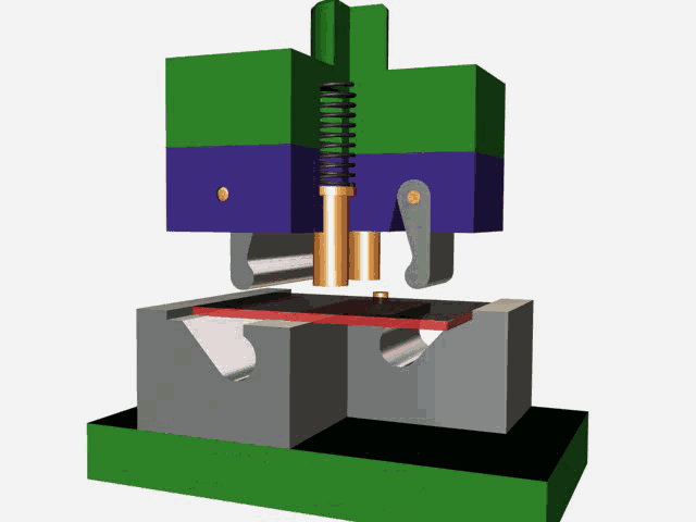
The most commonly used materials for stamping production are metallic materials (including ferrous and non-ferrous metals), but sometimes non-metallic materials are also used.
The ferrous metals include common carbon structural steels, high-quality carbon structural steels, alloy structural steels, carbon tool steels, stainless steels, electrical silicon steels, and the like;
Non-ferrous metals mainly include pure copper, brass, bronze and aluminum.
Non-metallic materials include cardboard, laminates, rubber sheets, plastic sheets, fiberboards, and mica.
Mold material
Metal mold is divided into:
Including stamping dies (such as blanking dies, bending dies, deep drawing dies, hole-opening dies, shrinkage dies, undulating dies, bulging dies, and plastic dies), forging dies (such as die forging dies, Upsetting molds, etc.), Extrusion dies, die casting dies, forging dies, etc.
Stamping die is divided into five grades according to the service life.
Level 1 is more than one million times.
Level 2 is 500,000---100 million times.
Level 3 is 300,000 - 500,000,
Level 4 is between 100,000 and 300,000 times.
Level 5 is less than 100,000 times. Grade 1 and 2 molds require steel materials that can be heat treated to a hardness of around HRC50.
Stamping die materials: steel, cemented carbide, steel bonded carbide, zinc-based alloys, low melting point alloy, aluminum bronze, polymer materials and the like. At present, most of the materials used to make stamping dies are mainly steel. The types of commonly used mold working part materials include: carbon tool steel, low alloy tool steel, high carbon high chromium or medium chromium tool steel, medium carbon alloy steel, high speed steel, matrix steel, hard alloy, steel cemented carbide Etc.
Testing standards
Before the mold design, the "Mold Design, Manufacturing, and Delivery Schedule" must be given. The schedules of the three major stages of mold design, mold manufacturing (wire cutting/heat treatment, fine grinding, etc.) and mold assembly/testing need to be listed in detail. , And the supplier organizes the technical review meeting; the table needs to list the mold assembly time and the time for the first tryout.
The tact time of the mould process is within 3s of the continuous die, The engineering die speed is 5s, and the design life guarantee is 1 million times. Special products, suppliers can not guarantee this requirement, can apply according to the actual situation.
Acceptance Criteria:
1. When the mold is delivered, it must be ensured that there are equal height blocks for each limit post to facilitate mold lifting. In the process of preventing the mold from being transported, the punches that partially meshed with the die are damaged.
2. The die body requires a firm structure to prevent the die from being too light and thin (such as the thin stripper plate) causing life-time defects during operation. The stress concentration problem of the material needs to be considered in all mold inserts. There must be no sharp corners.
3. All large parts of the mold need to consider lifting screw holes, Convenient mold maintenance.
4. The mold must be designed with error proofing.
5. The entire set of mold drawings must indicate the total weight.
6 mold must be designed to Automatic discharge nail (spring + top material pin), Prevents sticking of the workpiece.
7. The mold is based on the principles of easy human operation (operating habits), ease of maintenance, and safety.
8. In principle, the thickness of all plates (discharge plates, backing plates, etc.) of the mould shall not be less than 35mm.
9. The total assembly height must not exceed the upper limit of the mold slider adjustment.
NEXT:NONE