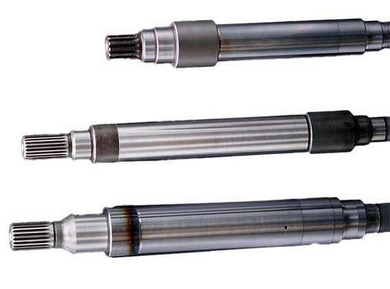
CNC Turning of Reducer Input Shaft
Reducer input shaft processing method and process
1. The present invention relates to input shaft CNC turning processing technology. Specifically, it relates to a reducer input shaft processing method that improves the accuracy of the reducer input shaft.
Background technique:
2. At present, new energy vehicle reducers mainly rely on splines in the input shaft to transmit torque and speed. The rotation of the input shaft drives the entire gearbox to work. The traditional input shaft machining method uses center hole positioning to CNC turn the outer circle, which does not consider the concentricity of the input shaft outer circle and splines. This processing method causes the concentricity of the spline and the outer circle of the bearing to be >0.05mm, causing the input shaft to move unbalanced during rotation and the dynamic balance effect is poor. As a result, the entire gearbox causes abnormal acceleration noise and idle noise during acceleration or deceleration.
Technical implementation elements:
3. The purpose of the present invention is to provide a method for processing the input shaft of a reducer. It can solve the problem of abnormal vibration of the outer circle of the bearing when the external spline shaft extends into the internal spline of the reducer input shaft for torque transmission.
4. The CNC turning of the present invention is implemented as follows:
5. A CNC turning method for the input shaft of a reducer. The processing method includes the following steps:
6. To process the internal splines of the input shaft, use an involute spline composite broach to process the tooth root and tooth side of the internal splines of the input shaft and then remove the tooth top;
7. Rough grind the outer circle, use a special mandrel to position the tooth top, and use the large diameter of the spline to expand and position. Rough grinding of the tooth tip outer circle set on the outer wall of the inner spline of the input shaft, and the stepped outer circle set on the long end of the input shaft;
8. Turn the center hole, clamp the rough-ground outer circle of the tooth tip and the outer circle of the step, and repair the center hole of the input shaft;
9. Precision grinding of the outer circle: The top of the clamping member is pressed against the center hole to process the second bearing installation position at the short end of the input shaft. The outer circle of the first bearing mounting position at the long end is finely ground.
10. In the preferred CNC turning of the present invention, the following steps are included after the above-mentioned input shaft internal spline machining:
11. Gear hobbing: hobbing the outer wall of the inner spline of the input shaft;
12. Heat treatment: perform heat treatment on the entire input shaft.
13. After processing the tooth root and tooth side in the above input shaft internal spline processing steps, the diameter of the internal spline hole is 18.88(+0.033^0)mm. The diameter of the inner spline hole after removing the tooth top is 19.02(+0.033^0)mm.
14. The above-mentioned special mandrels include:
15. The positioning expansion mandrel is provided with a first assembly frustum, and the end of the positioning expansion mandrel is provided with an external thread;
16. Positioning viscose expansion sleeve: set on the positioning expansion mandrel. The positioning adhesive expansion sleeve is provided with a plurality of clamping slits distributed in an annular array. Each clamping gap is provided with rubber filling the clamping gap, and the central axis of the positioning viscose expansion sleeve is provided with a penetrating first through hole. The first through hole includes a first frustum hole, a first cylindrical hole and a second frustum hole arranged in sequence, and the first frustum hole is connected to the first assembly frustum;
17. Press the taper sleeve, insert it from the assembly end on the same side as the positioning viscose expansion sleeve, and set it on the positioning expansion mandrel. One end of the compression taper sleeve is provided with a second assembly frustum, and the second assembly frustum matches the second frustum hole;
18. The compression nut is threadedly connected to the external thread, and the end face of the compression nut is pressed against the end face of the compression taper sleeve. When the compression nut continues to be screwed in, the compression taper sleeve squeezes the positioning viscose expansion sleeve to expand the positioning viscose expansion sleeve, so that the special mandrel and the internal spline tooth top are positioned together.
19. The diameter of the above-mentioned special mandrel is φ18.7±0.05mm in the free state, and the diameter expands to a maximum of φ19.4mm after being stressed.
20. In this processing method, the inner spline of the input shaft is machined and then expanded and positioned, and then the outer circle of the input shaft is machined. Then, based on the outer circle of the input shaft, the center hole is further repaired and the outer circle is finely ground. The processing method unifies the concentricity of the center hole, spline and outer circle, and unifies the center datum of the spline and grinding outer circle. The engine shaft does not produce abnormal vibration when transmitting torque to the input shaft, which greatly improves the noise level of the gearbox assembly.
Description of the drawings
21. In order to explain the technical solutions of the embodiments of the present invention more clearly. The drawings needed to be used in the embodiments will be briefly introduced below for easy understanding. The following drawings illustrate only certain embodiments of the invention and therefore should not be considered limiting of scope. For those of ordinary skill in the art, other relevant drawings can also be obtained based on these drawings without exerting creative efforts.
22. Figure 1 is a schematic structural diagram of the input shaft of the reducer in the spline pulling step in the embodiment of the present invention;
23. Figure 2 is a schematic structural diagram of the composite broach used in the spline drawing step of the embodiment of the present invention;
24. Figure 3 is a schematic structural diagram of the special mandrel for expansion and positioning in the step of rough grinding of the outer circle in the embodiment of the present invention;
25. Figure 4 is a schematic diagram of the product structure of the step of carving the center hole according to the embodiment of the present invention;
26. Figure 5 is a schematic diagram of the product structure of the outer circle fine grinding step according to the embodiment of the present invention.
27. Icon: Reducer input shaft 100, internal spline 101, gear processing position 102, step outer circle 103, first center hole 104, first bearing installation position 105, second center hole 106, second bearing installation position 107 ;
28. Involute spline composite broach 200, spline cutting teeth 210, flower circle cutting teeth 220, flower circle calibration teeth 230;
29. Special mandrel 300, positioning expansion mandrel 310, positioning adhesive expansion sleeve 320, compression taper sleeve 330, compression nut 340.


