Set the high-speed milling tool path for machining the fillet of structural parts
Conventional NC machining generally uses equal-cut thick cutting when formulating the tool path. That is, the radial depth of cut is a certain value during one pass. However, in the case of excessive milling of the rounded corners, the machining problem is large. The problem is particularly significant when milling thin-walled structures at high speeds. In the practice of high-speed milling of rounded corners, it can be seen that there is a significant change in the cutting force of the tool at the fillet (see Figure 1).
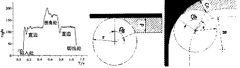
A method of refining the rounded tool path for rounding machine machining problems. In the case of equal-cutting and thick milling, when the tool transitions from a straight path to a circular path, the incision angle Qb increases (see Figures 2 and 3).
Corresponding to the figure has the following formula:
Cos(Qb)=1-Cl/r (1)
Cos(Qb)=1-Cc/r-Cc(r-0.5Cc)/rR (2)
Qb——— plunge angle;
Cl———the radial depth of cut during straight edge milling;
Cc—the radial depth of cut during fillet milling;
r——— milling cutter radius;
R———The radius of the tool center track at the fillet.
Obviously, when Cl=Cc, when the tool transitions from a straight path to a circular path. The contact area of the tool with the workpiece is increased due to an increase in the plunging angle, thereby causing a sudden increase in the cutting force and easily generating vibration. The sudden change of the cutting force causes the machining deformation of the tool and the workpiece to increase, and the dimensional error of the part is increased, and the cutting vibration generates a vibration pattern at the round corner, which affects the processing quality of the part.
The method of refining the rounded tool path. The idea is to keep the cutting angle of the tool constant during the pass, or to add a path to the tool, that is, to reduce the radial thickness of the tool at the round corner, so as to avoid the sudden change of the cutting force. The specific refinement tool path diagram is shown in Figures 4 and 5.
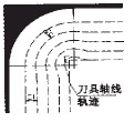
Figure 4 Schematic diagram of equal cutting angle tool path refinement
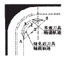
Figure 5 Schematic diagram of additional path refinement
The tool path refinement scheme at the milling fillet can effectively maintain stable cutting. Reduce machining distortion and possible cutting vibration caused by sudden changes in cutting force, and improve the processing quality of parts.
At the same time, the chip thickness is counter-clockwise from thin to thick. Due to the size effect of the cutting edge, when the cutting edge just touches the workpiece, the friction between the flank face and the workpiece is large, which is easy to cause vibration, and severe oblique vibrating will occur at the corner. Clockwise milling is just the opposite. Although the cutting force of the down-milling is slightly larger than the cutting force during the up-cut milling, there is no significant chattering when cutting the corners. However, when the clockwise milling is performed, the chip thickness is thick to thin, and the impact on the workpiece and the tool is large. When the machining is performed, the overhang of the tool is reduced as much as possible and the rigidity of the workpiece is increased.
figure 1 Cutting force change curve, figure 2 Straight edge milling diagram, image 3 Schematic diagram of milling rounded corners
A method of refining the rounded tool path for rounding machine machining problems. In the case of equal-cutting and thick milling, when the tool transitions from a straight path to a circular path, the incision angle Qb increases (see Figures 2 and 3).
Corresponding to the figure has the following formula:
Cos(Qb)=1-Cl/r (1)
Cos(Qb)=1-Cc/r-Cc(r-0.5Cc)/rR (2)
Qb——— plunge angle;
Cl———the radial depth of cut during straight edge milling;
Cc—the radial depth of cut during fillet milling;
r——— milling cutter radius;
R———The radius of the tool center track at the fillet.
Obviously, when Cl=Cc, when the tool transitions from a straight path to a circular path. The contact area of the tool with the workpiece is increased due to an increase in the plunging angle, thereby causing a sudden increase in the cutting force and easily generating vibration. The sudden change of the cutting force causes the machining deformation of the tool and the workpiece to increase, and the dimensional error of the part is increased, and the cutting vibration generates a vibration pattern at the round corner, which affects the processing quality of the part.
The method of refining the rounded tool path. The idea is to keep the cutting angle of the tool constant during the pass, or to add a path to the tool, that is, to reduce the radial thickness of the tool at the round corner, so as to avoid the sudden change of the cutting force. The specific refinement tool path diagram is shown in Figures 4 and 5.
Figure 4 Schematic diagram of equal cutting angle tool path refinement
Figure 5 Schematic diagram of additional path refinement
The tool path refinement scheme at the milling fillet can effectively maintain stable cutting. Reduce machining distortion and possible cutting vibration caused by sudden changes in cutting force, and improve the processing quality of parts.
At the same time, the chip thickness is counter-clockwise from thin to thick. Due to the size effect of the cutting edge, when the cutting edge just touches the workpiece, the friction between the flank face and the workpiece is large, which is easy to cause vibration, and severe oblique vibrating will occur at the corner. Clockwise milling is just the opposite. Although the cutting force of the down-milling is slightly larger than the cutting force during the up-cut milling, there is no significant chattering when cutting the corners. However, when the clockwise milling is performed, the chip thickness is thick to thin, and the impact on the workpiece and the tool is large. When the machining is performed, the overhang of the tool is reduced as much as possible and the rigidity of the workpiece is increased.


