Continuous Stamping Design Of Metal Shell Parts
The shape and size of the car door glass lifter housing parts. As shown in Figure 8.2.1,
The material is 08 steel plate, plate thickness 1.5mm, mass production.
Stamping production, it requires the preparation of a stamping process.
8.2.1 Process analysis of stamping parts
First, you must fully understand the application and technical requirements of the product, and conduct process analysis.
The glass on the car door is lifted or lowered by the lifter.
The assembly diagram of the lifter components is shown in Figure 8.2.2. The stamped part is the outer casing 5 of it. The transmission mechanism of the elevator is housed in the outer casing, and is riveted to the door seat plate by three uniformly distributed small holes φ 3.2mm on the outer casing flange. The drive shaft 6 is mounted on the support portion of the right end hole φ 16.5mm with the clearance of I T11. The brake torsion spring 3, the linkage piece 9 and the spindle 4 are coupled with the pinion 11 to rock the handle 7. The drive shaft transmits power to the pinion, and then drives the large gear 12 to push the door glass up and down.
The stampings are stamped from 1.5mm steel plates to ensure adequate rigidity and strength.
The main mating dimensions of the inner cavity of the housing are φ 16.5 mm, φ 22.3 mm and 16 mm are IT11-IT12.
In order to ensure the coaxiality between the support part and the sleeve after riveting and fixing, the relative position between the three φ 3.2mm small holes and φ 16.5mm is accurate, and the diameter of the small hole center circle is φ 42 ± 0.1mm. T10 level.
This part is a rotating body whose shape is characterized by a flanged cylindrical piece.
The main shape and size can be obtained by a drawing process such as drawing, flanging, punching, and the like.
As the drawing size, the relative values are suitable, and the drawing process is better.
The tolerance requirements for φ 22.3 mm and 16 mm are too high. The radius of the fillet at the bottom and the mouth of the deep drawing piece is also small, so it should be added after the drawing, and the mold with high precision and small gap should be used.
The accuracy of the center circle diameter of the three small holes φ 3.2 mm is 42 ± 0.1mm. According to the technical analysis of the blanking parts, the inner diameter of φ 22.3 mm should be positioned, and the high-precision (IT7 or higher) die should be punched out simultaneously in one process.
Figure 8.2.1 Glass lifter metal casing
Figure 8.2.2 Assembly diagram of the glass lifter housing
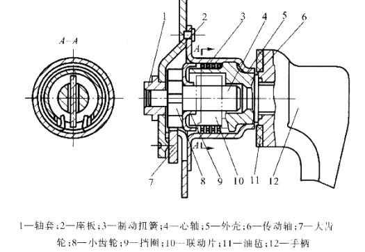
Figure 8.2.3 Forming scheme at the bottom of the casing
a) cut; b) punching; c) punching flanging
Figure 8.2.4 Shape and size of the semi-finished product before the flange
The material is 08 steel plate, plate thickness 1.5mm, mass production.
Stamping production, it requires the preparation of a stamping process.
8.2.1 Process analysis of stamping parts
First, you must fully understand the application and technical requirements of the product, and conduct process analysis.
The glass on the car door is lifted or lowered by the lifter.
The assembly diagram of the lifter components is shown in Figure 8.2.2. The stamped part is the outer casing 5 of it. The transmission mechanism of the elevator is housed in the outer casing, and is riveted to the door seat plate by three uniformly distributed small holes φ 3.2mm on the outer casing flange. The drive shaft 6 is mounted on the support portion of the right end hole φ 16.5mm with the clearance of I T11. The brake torsion spring 3, the linkage piece 9 and the spindle 4 are coupled with the pinion 11 to rock the handle 7. The drive shaft transmits power to the pinion, and then drives the large gear 12 to push the door glass up and down.
The stampings are stamped from 1.5mm steel plates to ensure adequate rigidity and strength.
The main mating dimensions of the inner cavity of the housing are φ 16.5 mm, φ 22.3 mm and 16 mm are IT11-IT12.
In order to ensure the coaxiality between the support part and the sleeve after riveting and fixing, the relative position between the three φ 3.2mm small holes and φ 16.5mm is accurate, and the diameter of the small hole center circle is φ 42 ± 0.1mm. T10 level.
This part is a rotating body whose shape is characterized by a flanged cylindrical piece.
The main shape and size can be obtained by a drawing process such as drawing, flanging, punching, and the like.
As the drawing size, the relative values are suitable, and the drawing process is better.
The tolerance requirements for φ 22.3 mm and 16 mm are too high. The radius of the fillet at the bottom and the mouth of the deep drawing piece is also small, so it should be added after the drawing, and the mold with high precision and small gap should be used.
The accuracy of the center circle diameter of the three small holes φ 3.2 mm is 42 ± 0.1mm. According to the technical analysis of the blanking parts, the inner diameter of φ 22.3 mm should be positioned, and the high-precision (IT7 or higher) die should be punched out simultaneously in one process.
Figure 8.2.1 Glass lifter metal casing
Figure 8.2.2 Assembly diagram of the glass lifter housing
1, bushings. 2, seat plate. 3, brake torsion spring. 4, the mandrel. 5, the outer casing. 6, the drive shaft. 7, big gear. 8, pinion. 9, the retaining ring. 10, linkage film.11, linoleum. 12, the handle
8.2.2 Determination of stamping process
one. Analysis and comparison of process plans
The shape of the outer casing indicates that it is a deep drawing piece, so drawing is a basic process.
The three small holes in the flange are completed by a punching process.
The forming of the part φ 16.5 mm (see the right side of Figure 8.2.1) can be done in three ways:
1, can use Step deep drawing, turning to the bottom;
2, after the Step deep drawing can be used, stamping removes the bottom;
3, You can use the method of drawing, Punching bottom hole, and then flanging. (See Figure 8.2.3)
The first method has a higher quality at the bottom of the turning but has a lower productivity. It is not easy to use when the bottom of the part is not high.
The second method requires the bottom fillet radius to be close to zero before stamping to remove the bottom, so an additional shaping process is required and the quality is not easily guaranteed.
The third method, although the quality of the end of the flange is not as good as the first two, but the production efficiency is high, and the material is saved.
Since the tolerance of the housing height dimension of 21 mm is not high, the flanging process can fully guarantee the technical requirements of the parts, so it is reasonable to use the method of deep drawing and then punching and flanging.
Figure 8.2.3 Forming scheme at the bottom of the casing
a) cut; b) punching; c) punching flanging
two. Determination of the process plan
• Calculate blank size
Before calculating the blank size, it is necessary to determine the shape and size of the semi-finished product before the flanging, and calculate the degree of deformation of the flanging. Referring to FIG. 8.2.1, the height dimension of the parts at φ 16.5 mm is: H = 21-16 = 5mm.
According to the calculation formula of the flanging process, the flanging coefficient K is:
The flange height H = 5 mm; cuff diameter D = 16.5 + 1.5 = 18mm; flanging radius r = 1 mm; material thickness t = 1.5mm into the above equation to obtain the coefficient flange:

Pre-punched hole diameter d = DK = 11 mm , d / t = 11 / 1.5 = 7.33
Check the limit value of the flanging coefficient. When the pre-punch is punched with a cylindrical punch, the limit flanging coefficient [ K ]=0.5. Now 0.61>0.5, it is possible to obtain a height of H = 5 mm by directly flanging after punching. The shape and dimensions of the drawn parts before the flanging are shown in Figure 8.2.4.
In order to calculate the blank size, the trim allowance must also be determined. Because the flange diameter d = 50mm, the drawing diameter d = 23.8mm, so ,Check data drawing process, to obtain the remainder of the flange edging δ = 1.8 mm, the actual diameter of the flange d '= d projections projecting +2 δ = (50 + 3.6) mm ≈ 54 mm. The blank diameter D is calculated according to the following formula:
 =
= ≈ 65 mm
• Calculate blank size
Before calculating the blank size, it is necessary to determine the shape and size of the semi-finished product before the flanging, and calculate the degree of deformation of the flanging. Referring to FIG. 8.2.1, the height dimension of the parts at φ 16.5 mm is: H = 21-16 = 5mm.
According to the calculation formula of the flanging process, the flanging coefficient K is:
The flange height H = 5 mm; cuff diameter D = 16.5 + 1.5 = 18mm; flanging radius r = 1 mm; material thickness t = 1.5mm into the above equation to obtain the coefficient flange:
Pre-punched hole diameter d = DK = 11 mm , d / t = 11 / 1.5 = 7.33
Check the limit value of the flanging coefficient. When the pre-punch is punched with a cylindrical punch, the limit flanging coefficient [ K ]=0.5. Now 0.61>0.5, it is possible to obtain a height of H = 5 mm by directly flanging after punching. The shape and dimensions of the drawn parts before the flanging are shown in Figure 8.2.4.
In order to calculate the blank size, the trim allowance must also be determined. Because the flange diameter d = 50mm, the drawing diameter d = 23.8mm, so
,Check data drawing process, to obtain the remainder of the flange edging δ = 1.8 mm, the actual diameter of the flange d '= d projections projecting +2 δ = (50 + 3.6) mm ≈ 54 mm. The blank diameter D is calculated according to the following formula:=≈ 65 mmFigure 8.2.4 Shape and size of the semi-finished product before the flange
2 . Calculate the number of stamping drawing
Because t / D = 2.3% ,
,  , Initially r 1 ≈ (4 ~ 5) t, from "stamping Manual" look-up table can be obtained limit drawing coefficient [m 1] = 0.44, [m 2] = 0.75, and the [m 1] [m 2] =0.44 × 0.75=0.33, so m total > [ m 1 ][ m 2 ]. Require two drawing, taking n = 2.
When performing drawing using the drawing coefficient close to the limit, the need to use a larger radius, to guarantee the quality of the drawing. At present, the material thickness of the part is t = 1.5mm, the radius of the fillet is r = 2.55 mm, which is about 1.5 t, which is too small, and the diameter of the part is small. It is difficult to meet the requirements of the parts by two deep drawing. Therefore, it is necessary to add a shaping process after two deep drawing to obtain a smaller mouth and bottom fillet radius.
In practical applications, three deep drawing processes can be used to reduce the radius of the fillet in turn. The total drawing coefficient m total = 0.366 is assigned to the three-way drawing process, and m 1 = 0.56 , m 2 = 0.805 , m 3 = 0.812 can be selected.
m 1 × m 2 × m 3 =0.56 × 0.805 × 0.812=0.366
3 . Process combination and sequence determination
For the stamping parts with many processes such as the outer casing, the basic process of the parts can be determined first, and then the possible combination sorting of all the basic processes can be considered. The various process schemes thus obtained are analyzed and compared, from which the best solution suitable for the actual production is determined.
The basic process of the outer casing is:
Blanking φ 65 mm, first draw,
The second deep drawing (see Figure 8-11b),
The third deep drawing (see Figure 8.2.5c) and the bottom hole φ 11 mm (see Figure 8.2.5d),
Flanging φ 16.5 mm (see Figure 8.2.5e),
Punch three small holes φ 3.2 mm (see Figure 8.2.5f),
Trimming φ 50 mm (see Figure 8.2.5g).
A total of eight basic processes, according to which the following five process options can be discharged:
Option 1: The blanking is combined with the first drawing (see Figure 8.2.5a), and the rest is based on the basic process.
Option II:
The blanking is combined with the first drawing, and the φ 11 mm bottom hole is combined with the flange (see Figure 8.2.6a). The three small holes φ 3.2 mm are combined with the trimming (see Figure 8.2.6b), and the rest are based on the basic process. .
third solution:
The blanking is combined with the first drawing, and the φ 11 mm bottom hole is combined with the three small holes φ 3.2 mm (see Figure 8.2.7a). The flange is trimmed with the trim (see Figure 8.2.7b), and the rest is based on the basic process.
Option 4:
Blanking, first deep drawing and punching φ 11 mm bottom hole composite (see Figure 8.2.8), the rest according to the basic process. Option 5: Use progressive die or stamping on a multi-station automatic press.
Analysis and comparison of the above five schemes, it can be seen that in scheme 2, the punching φ 11mm hole is combined with the flange, due to the small thickness of the mold wall
 mm,It is smaller than the minimum wall thickness of 3.8 mm between the convex and concave molds, and the mold is easily damaged. Punching three small holes φ 3.2 mm combined with trimming, there is also the problem that the mold wall is too thin. at this time
 mm, Therefore, it should not be used.
In option three,
Although solving the contradiction that the above mold wall is too thin, However, when the φ 11 mm bottom hole is combined with the three small holes φ 3.2 mm and the flange and the trim are combined, their cutting edges are not on the same plane, and the wear speed is different. This can cause inconvenience to grinding, and it is difficult to maintain relative position after grinding.
In option four,
Blanking, first deep drawing and punching φ 11 mm bottom hole composite, punching die and deep drawing punch are integrated, which will also cause difficulty in grinding. In particular, after the bottom hole is drilled twice and three times, once the hole diameter changes, it will affect the height dimension of the flange and the quality of the flange portion.
The fifth scheme adopts a progressive die or a multi-station automatic feeding device, which has high production efficiency. The mold structure is complex, the manufacturing cycle is long, and the cost is high. Therefore, it is only suitable for mass production.
Scheme 1 does not have the above-mentioned shortcomings, but the degree of compounding is low and the production efficiency is low. However, the single-process mold has a simple structure and low manufacturing cost, which is reasonable in small and medium batch production, so it is decided to adopt the first scheme. In the third deep drawing and flanging process, when the stamping stroke is nearing the end, the mold can be rigidly pressed against the workpiece to form a shaping effect, so no additional shaping process is required.
Because t / D = 2.3%
, , Initially r 1 ≈ (4 ~ 5) t, from "stamping Manual" look-up table can be obtained limit drawing coefficient [m 1] = 0.44, [m 2] = 0.75, and the [m 1] [m 2] =0.44 × 0.75=0.33, so m total > [ m 1 ][ m 2 ]. Require two drawing, taking n = 2.When performing drawing using the drawing coefficient close to the limit, the need to use a larger radius, to guarantee the quality of the drawing. At present, the material thickness of the part is t = 1.5mm, the radius of the fillet is r = 2.55 mm, which is about 1.5 t, which is too small, and the diameter of the part is small. It is difficult to meet the requirements of the parts by two deep drawing. Therefore, it is necessary to add a shaping process after two deep drawing to obtain a smaller mouth and bottom fillet radius.
In practical applications, three deep drawing processes can be used to reduce the radius of the fillet in turn. The total drawing coefficient m total = 0.366 is assigned to the three-way drawing process, and m 1 = 0.56 , m 2 = 0.805 , m 3 = 0.812 can be selected.
m 1 × m 2 × m 3 =0.56 × 0.805 × 0.812=0.366
3 . Process combination and sequence determination
For the stamping parts with many processes such as the outer casing, the basic process of the parts can be determined first, and then the possible combination sorting of all the basic processes can be considered. The various process schemes thus obtained are analyzed and compared, from which the best solution suitable for the actual production is determined.
The basic process of the outer casing is:
Blanking φ 65 mm, first draw,
The second deep drawing (see Figure 8-11b),
The third deep drawing (see Figure 8.2.5c) and the bottom hole φ 11 mm (see Figure 8.2.5d),
Flanging φ 16.5 mm (see Figure 8.2.5e),
Punch three small holes φ 3.2 mm (see Figure 8.2.5f),
Trimming φ 50 mm (see Figure 8.2.5g).
A total of eight basic processes, according to which the following five process options can be discharged:
Option 1: The blanking is combined with the first drawing (see Figure 8.2.5a), and the rest is based on the basic process.
Option II:
The blanking is combined with the first drawing, and the φ 11 mm bottom hole is combined with the flange (see Figure 8.2.6a). The three small holes φ 3.2 mm are combined with the trimming (see Figure 8.2.6b), and the rest are based on the basic process. .
third solution:
The blanking is combined with the first drawing, and the φ 11 mm bottom hole is combined with the three small holes φ 3.2 mm (see Figure 8.2.7a). The flange is trimmed with the trim (see Figure 8.2.7b), and the rest is based on the basic process.
Option 4:
Blanking, first deep drawing and punching φ 11 mm bottom hole composite (see Figure 8.2.8), the rest according to the basic process. Option 5: Use progressive die or stamping on a multi-station automatic press.
Analysis and comparison of the above five schemes, it can be seen that in scheme 2, the punching φ 11mm hole is combined with the flange, due to the small thickness of the mold wall
mm,It is smaller than the minimum wall thickness of 3.8 mm between the convex and concave molds, and the mold is easily damaged. Punching three small holes φ 3.2 mm combined with trimming, there is also the problem that the mold wall is too thin. at this timemm, Therefore, it should not be used.In option three,
Although solving the contradiction that the above mold wall is too thin, However, when the φ 11 mm bottom hole is combined with the three small holes φ 3.2 mm and the flange and the trim are combined, their cutting edges are not on the same plane, and the wear speed is different. This can cause inconvenience to grinding, and it is difficult to maintain relative position after grinding.
In option four,
Blanking, first deep drawing and punching φ 11 mm bottom hole composite, punching die and deep drawing punch are integrated, which will also cause difficulty in grinding. In particular, after the bottom hole is drilled twice and three times, once the hole diameter changes, it will affect the height dimension of the flange and the quality of the flange portion.
The fifth scheme adopts a progressive die or a multi-station automatic feeding device, which has high production efficiency. The mold structure is complex, the manufacturing cycle is long, and the cost is high. Therefore, it is only suitable for mass production.
Scheme 1 does not have the above-mentioned shortcomings, but the degree of compounding is low and the production efficiency is low. However, the single-process mold has a simple structure and low manufacturing cost, which is reasonable in small and medium batch production, so it is decided to adopt the first scheme. In the third deep drawing and flanging process, when the stamping stroke is nearing the end, the mold can be rigidly pressed against the workpiece to form a shaping effect, so no additional shaping process is required.