Design And Selection Of Mold Parts
1) Determine the dimensions of the concave die.
The blanking die adopts the integral concave die and the wire cutting machine tool. When arranging the position of the concave die on the die base, the pressure center and the handle center should be overlapped according to the data of the pressure center. The dimensions are calculated according to the relevant formula.
The thickness of the concave die H=KL=0.38×30=11.4(mm)
Take the die thickness H=15mm
Die wall thickness c=(1.5~2)H=(22.5~30)mm
Setting the thickness of die wall c=25mm
Concave die width B=L+2c=30+25×2=80(mm)
Setting concave die width B=80mm
The length of the concave die L=L+2S2=30+2×25=80(mm)
Setting concave die length L=80mm
Overall dimension of concave die L×B×H=80mm×80mm×15mm
2) Choose a typical combination
The shape of the punch is 80mm × 80mm × 15mm, so the typical combination is: 80x80x180~220 (GB2873.2-81)
7.2 concave mold body design
1) hole position. The position being punched from the layout chart is obtained.
2) type of pore size. Obtained by cutting edge size.
3) Blade form. Adopt straight cylinder type, reverse hole enlargement, vertical wall height check 1-26 for 10mm.
4) Pin hole. The size, number and position of each screw hole and pin hole can be found from the typical standard combination GB2873.2;
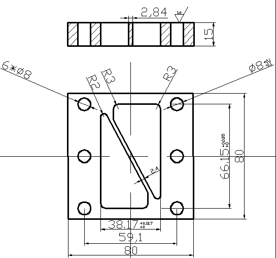
5) Material and technical requirements. The material is CrWMn, heat treated 60~64HRC, and the surface roughness is shown in the figure below;
6) Die part drawing. The design result is drawn into a concave part drawing, as shown below.
6) Punch part drawing. The drawing of the die part is drawn from the design results, as shown below.
2. Design of convex and concave mold
1) The wall thickness of the convex and concave mold. The minimum wall thickness of the convex and concave molds (75-40)/2=17.5mm meets the minimum wall thickness requirement of the flip-chip composite mold;
2) The structural form of the convex and concave mold. With a straight-through type, the shape is obtained from the position where the die-cutting pattern is punched. Fixing method: using screws and fixing plate fixing method;
3) The size of the working part of the convex and concave mold. Obtained from the calculation of the edge size;
4) Calculation of the length of the convex and concave mold. Reference standard standard combination GB2873.2 obtained fixed plate mating section h1= 20mm, unloading plate h2= 14mm, elastic component mounting height t h3= 20mm, unloading plate higher than convex and concave die 1mm, get convex die length:
L= h1+h2+t-1=53mm
5) Material and technical requirements. The material is Cr12, the heat treatment hardness is 58~62HRC, and the surface roughness is as follows;
6) Drawing of the convex and concave parts. The design result is drawn into a concave and concave part drawing, as shown in the following figure.
3. Design of unloading parts
1) Design of the unloading plate
The unloading plate is made of 45 steel, and the quenching hardness is 40-45HRC. The contour of the unloading plate is the same as that of the blanking die, and the thickness is 15mm.
2) Selection of unloading screws
Four unloading screws are installed on the unloading plate, nominal diameter is 12 mm, thread part is M12 *55 mm, unloading screw tail should leave enough travel space to ensure the normal movement of unloading. After the unloading screw is tightened, the unloading screw plate shall be 1 mm beyond the end face of the die. When there is an error, the discharging screw plate shall be adjusted by installing a gasket between the screw and the discharging plate.
4. Selection of mould frame and other components
According to the outline size of the concave die, choose the mould frame specification. Select one big, one small, two sets of guide sleeves and guide posts.
The guide column d/mm×L/mm is Φ32mm×2000mm;
Guide sleeve d/mm×L/mm×D/mm is Φ32mm×110mm×45mm;
The upper die base thickness H1 is 40mm, the backing plate thickness is 10mm, the fixed plate thickness is 20mm, the unloading plate thickness is 14mm, the concave die thickness is 25mm, and the lower die seat thickness is 45mm.
Mold closing height H
H=40+10+20+14+25+45-2=152(mm)
5, check the mold closing height and the relevant parameters of the press
5.1 check mold closing height
Mold closing height H should be satisfied
Hmin-H1+10≤H≤Hmax-H1-5 (Equation 8-1)
Where Hmax—the maximum closing height of the press;
Hmin—the minimum closing height of the press;
H1—pad thickness.
According to the J23 - 25 of the selected press, the parameter table of the check press is:
Hmax=320mm, Hmin=180mm, H1=50mm
Bring the above data into Equation 7-1,
140<H<265
After the mold closing height H=207mm is calculated, within 140mm-265mm, the open press machine J23-25 meets the requirements.
The blanking die adopts the integral concave die and the wire cutting machine tool. When arranging the position of the concave die on the die base, the pressure center and the handle center should be overlapped according to the data of the pressure center. The dimensions are calculated according to the relevant formula.
The thickness of the concave die H=KL=0.38×30=11.4(mm)
Take the die thickness H=15mm
Die wall thickness c=(1.5~2)H=(22.5~30)mm
Setting the thickness of die wall c=25mm
Concave die width B=L+2c=30+25×2=80(mm)
Setting concave die width B=80mm
The length of the concave die L=L+2S2=30+2×25=80(mm)
Setting concave die length L=80mm
Overall dimension of concave die L×B×H=80mm×80mm×15mm
2) Choose a typical combination
The shape of the punch is 80mm × 80mm × 15mm, so the typical combination is: 80x80x180~220 (GB2873.2-81)
7.2 concave mold body design
1) hole position. The position being punched from the layout chart is obtained.
2) type of pore size. Obtained by cutting edge size.
3) Blade form. Adopt straight cylinder type, reverse hole enlargement, vertical wall height check 1-26 for 10mm.
4) Pin hole. The size, number and position of each screw hole and pin hole can be found from the typical standard combination GB2873.2;
5) Material and technical requirements. The material is CrWMn, heat treated 60~64HRC, and the surface roughness is shown in the figure below;
6) Die part drawing. The design result is drawn into a concave part drawing, as shown below.
7.3 Punching punch design
1) Punch check. The section size of punch is large, and strength and stiffness can not be checked.
2) The structural form of punch. The convex mold of the circular interface is ladder type and the standard GB2873.2 is used. Fixed plate fixation was adopted.
3) the size of the work part of the punch. Obtained by cutting edge size.
4) Calculation of the length of the punch. Check the standard GB2873.2, get the convex mold fixed plate = 20mm, hollow pad h2= 12mm, the punch thickness is calculated h3= 25mm, then L = h1+ h2+h3 =12+4+31=47mm.
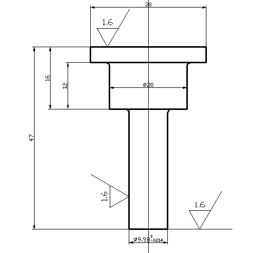
5) Material and technical requirements. The material is selected from T10A, and the heat treatment hardness is 58~62HRC;1) Punch check. The section size of punch is large, and strength and stiffness can not be checked.
2) The structural form of punch. The convex mold of the circular interface is ladder type and the standard GB2873.2 is used. Fixed plate fixation was adopted.
3) the size of the work part of the punch. Obtained by cutting edge size.
4) Calculation of the length of the punch. Check the standard GB2873.2, get the convex mold fixed plate = 20mm, hollow pad h2= 12mm, the punch thickness is calculated h3= 25mm, then L = h1+ h2+h3 =12+4+31=47mm.
6) Punch part drawing. The drawing of the die part is drawn from the design results, as shown below.
2. Design of convex and concave mold
1) The wall thickness of the convex and concave mold. The minimum wall thickness of the convex and concave molds (75-40)/2=17.5mm meets the minimum wall thickness requirement of the flip-chip composite mold;
2) The structural form of the convex and concave mold. With a straight-through type, the shape is obtained from the position where the die-cutting pattern is punched. Fixing method: using screws and fixing plate fixing method;
3) The size of the working part of the convex and concave mold. Obtained from the calculation of the edge size;
4) Calculation of the length of the convex and concave mold. Reference standard standard combination GB2873.2 obtained fixed plate mating section h1= 20mm, unloading plate h2= 14mm, elastic component mounting height t h3= 20mm, unloading plate higher than convex and concave die 1mm, get convex die length:
L= h1+h2+t-1=53mm
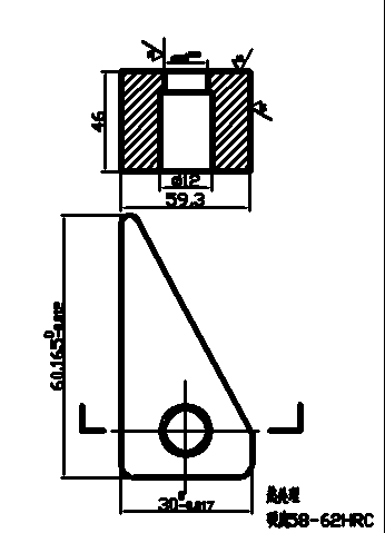
5) Material and technical requirements. The material is Cr12, the heat treatment hardness is 58~62HRC, and the surface roughness is as follows;
6) Drawing of the convex and concave parts. The design result is drawn into a concave and concave part drawing, as shown in the following figure.
3. Design of unloading parts
1) Design of the unloading plate
The unloading plate is made of 45 steel, and the quenching hardness is 40-45HRC. The contour of the unloading plate is the same as that of the blanking die, and the thickness is 15mm.
2) Selection of unloading screws
Four unloading screws are installed on the unloading plate, nominal diameter is 12 mm, thread part is M12 *55 mm, unloading screw tail should leave enough travel space to ensure the normal movement of unloading. After the unloading screw is tightened, the unloading screw plate shall be 1 mm beyond the end face of the die. When there is an error, the discharging screw plate shall be adjusted by installing a gasket between the screw and the discharging plate.
4. Selection of mould frame and other components
According to the outline size of the concave die, choose the mould frame specification. Select one big, one small, two sets of guide sleeves and guide posts.
The guide column d/mm×L/mm is Φ32mm×2000mm;
Guide sleeve d/mm×L/mm×D/mm is Φ32mm×110mm×45mm;
The upper die base thickness H1 is 40mm, the backing plate thickness is 10mm, the fixed plate thickness is 20mm, the unloading plate thickness is 14mm, the concave die thickness is 25mm, and the lower die seat thickness is 45mm.
Mold closing height H
H=40+10+20+14+25+45-2=152(mm)
5, check the mold closing height and the relevant parameters of the press
5.1 check mold closing height
Mold closing height H should be satisfied
Hmin-H1+10≤H≤Hmax-H1-5 (Equation 8-1)
Where Hmax—the maximum closing height of the press;
Hmin—the minimum closing height of the press;
H1—pad thickness.
According to the J23 - 25 of the selected press, the parameter table of the check press is:
Hmax=320mm, Hmin=180mm, H1=50mm
Bring the above data into Equation 7-1,
140<H<265
After the mold closing height H=207mm is calculated, within 140mm-265mm, the open press machine J23-25 meets the requirements.


