Analysis of Stamping Process and Die Design for Heavy Plate Material
Through the side plate parts of 10mm thick sheet, blanking process analysis, Die using a straight edge as a dry and a combination of the oblique edge, reducing the punching force. For a similar thick sheet blanking has a certain reference value.
Keywords: thick plate material, die form, die design
Case Analysis
Figure 1 is a side panel part of a device diagram, material is Q235A, 10mm thick steel plate. The part was originally stamped with a common blanking die, and the result was that the die was damaged after less than a hundred stampings. After being processed by heating red punching, the die has not been damaged, but the accuracy, surface quality and roughness of the stamped parts are not satisfactory. The oxide scale produced on the surface of the stamped parts can not meet the requirements after the painting, and the process is complicated, the labor intensity is high, and the stamping parts cost is high.
To this end, Kangding engineers carry out careful process analysis on the stamping of parts. At the same time, according to the company's existing presses (JB36-250t) and the required stamping force of parts, The form of concave die combined with straight edge and oblique edge is adopted to reduce punching force and achieve satisfactory effect after stamping.
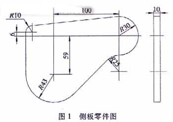
Figure 1
2. Process Analysis
The part is based on the punching force formula for thick sheet:
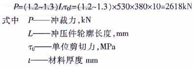
From the formula, the required blanking force for the part is 2618 kN.
Obviously, the nominal pressure of the company's existing presses (JB36-250t) is less than the required blanking force of the parts.
In view of this problem, a serious process analysis of the parts is carried out. It is considered that the cutting force required to reduce the parts can be processed with the existing press (JB36 250t) of the company.
According to the current data, there are three ways to reduce the punching force:
(1) slanting blade blanking method,
(2) red flush blanking,
(3) step punch blanking.
And the 3, The punching method of ladder punch is mainly used for blanking of multiple surfaces and is not suitable for this part. The punching method of ladder punch is mainly used for blanking of multiple surfaces and is not suitable for this part. Moreover, the introduction of these three kinds of processing methods is relative to the round surface, and the introduction of the curve surface processing is not introduced.
When the blanking die is punched out by the flat mouth, the shearing action is along the contour of the entire part and the shearing action occurs simultaneously, so the required blanking force is larger.
At the same time, the oblique edge punching method will cause the stamping parts to bend and wrinkle when punching, and the punching edge is also very easy to damage.
The red punching method produces oxide scale during stamping, the stamping precision, surface quality and roughness value are not ideal, and the process is complicated, labor intensity is great, and the cost of stamping parts is increased. When the blanking die is punched out by the flat mouth, the shearing action is along the contour of the entire part and the shearing action occurs simultaneously, so the required blanking force is larger. For this reason, according to the characteristics of the parts, the overall contour perimeter of the part is divided into 3 equal parts.
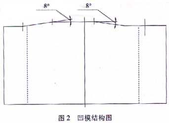
The form of the external oblique concave die combined with the straight blade edge and the oblique edge is adopted, as shown in Figure 2.
This form of die, when punching, the material is gradually separated along the length of the contour at different stroke heights. The required punching force is calculated according to the straight edge and bevel edge cutting formulas:
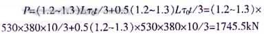
From the above calculations, it can be seen that, obviously, with this type of die, its punching force is reduced by 1/3. The company's existing press machine (JB36-250t) fully meets its demand.
3. Mold structure
The mold structure is shown in Figure 3.
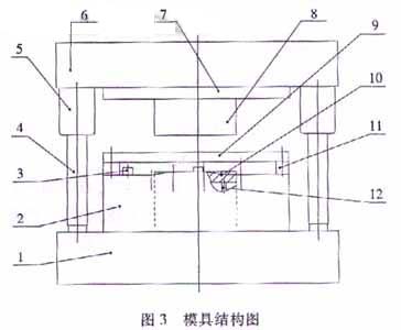
1. die shoe
2. Die
3. Positioning board
4. Guide posts
5. Guide sleeve
6. Die holder
7. Fixed board
8. terrace die
9. Stripper board
10. Push board
11. Pad
12. Top rod
4. Conclusion
There is no information about the form of the concave form of the curved surface of the straight blade and the oblique edge. The mold has been put into mass production and the use effect is good. For a similar thick sheet blanking has a great reference value.
Keywords: thick plate material, die form, die design
Case Analysis
Figure 1 is a side panel part of a device diagram, material is Q235A, 10mm thick steel plate. The part was originally stamped with a common blanking die, and the result was that the die was damaged after less than a hundred stampings. After being processed by heating red punching, the die has not been damaged, but the accuracy, surface quality and roughness of the stamped parts are not satisfactory. The oxide scale produced on the surface of the stamped parts can not meet the requirements after the painting, and the process is complicated, the labor intensity is high, and the stamping parts cost is high.
To this end, Kangding engineers carry out careful process analysis on the stamping of parts. At the same time, according to the company's existing presses (JB36-250t) and the required stamping force of parts, The form of concave die combined with straight edge and oblique edge is adopted to reduce punching force and achieve satisfactory effect after stamping.
Figure 1
2. Process Analysis
The part is based on the punching force formula for thick sheet:
From the formula, the required blanking force for the part is 2618 kN.
Obviously, the nominal pressure of the company's existing presses (JB36-250t) is less than the required blanking force of the parts.
In view of this problem, a serious process analysis of the parts is carried out. It is considered that the cutting force required to reduce the parts can be processed with the existing press (JB36 250t) of the company.
According to the current data, there are three ways to reduce the punching force:
(1) slanting blade blanking method,
(2) red flush blanking,
(3) step punch blanking.
And the 3, The punching method of ladder punch is mainly used for blanking of multiple surfaces and is not suitable for this part. The punching method of ladder punch is mainly used for blanking of multiple surfaces and is not suitable for this part. Moreover, the introduction of these three kinds of processing methods is relative to the round surface, and the introduction of the curve surface processing is not introduced.
When the blanking die is punched out by the flat mouth, the shearing action is along the contour of the entire part and the shearing action occurs simultaneously, so the required blanking force is larger.
At the same time, the oblique edge punching method will cause the stamping parts to bend and wrinkle when punching, and the punching edge is also very easy to damage.
The red punching method produces oxide scale during stamping, the stamping precision, surface quality and roughness value are not ideal, and the process is complicated, labor intensity is great, and the cost of stamping parts is increased. When the blanking die is punched out by the flat mouth, the shearing action is along the contour of the entire part and the shearing action occurs simultaneously, so the required blanking force is larger. For this reason, according to the characteristics of the parts, the overall contour perimeter of the part is divided into 3 equal parts.
The form of the external oblique concave die combined with the straight blade edge and the oblique edge is adopted, as shown in Figure 2.
This form of die, when punching, the material is gradually separated along the length of the contour at different stroke heights. The required punching force is calculated according to the straight edge and bevel edge cutting formulas:
From the above calculations, it can be seen that, obviously, with this type of die, its punching force is reduced by 1/3. The company's existing press machine (JB36-250t) fully meets its demand.
3. Mold structure
The mold structure is shown in Figure 3.
1. die shoe
2. Die
3. Positioning board
4. Guide posts
5. Guide sleeve
6. Die holder
7. Fixed board
8. terrace die
9. Stripper board
10. Push board
11. Pad
12. Top rod
4. Conclusion
There is no information about the form of the concave form of the curved surface of the straight blade and the oblique edge. The mold has been put into mass production and the use effect is good. For a similar thick sheet blanking has a great reference value.


