Precautions for Stamping Design,Metal stamping
(A) stamping material selection and parts layout
(1) Material selection
According to the thickness, strength, elasticity requirements, choose the right material for different applications.
(2) The layout of stamping parts
Optimize the design, rationalize the layout, and strive for the adoption of waste-free or less-scrap arrangements.
(3) Shape of stamping
In the case of meeting product requirements, it should be as simple and symmetrical as possible to minimize waste.
(b) Part thickness and strengthening rib
(1) Thickness
In order to ensure the life of the mold, the quality of the product and the ordering of materials on the market, the thickness of the stamped material should take the following range:
Iron/stainless steel: 0.1≤t≤3 (mm)
Copper/aluminum: 0.1≤t≤4 (mm)
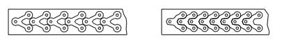
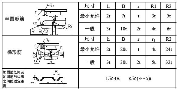
(2) Strengthening rib
For larger or longer sheet metal parts, the strengthening rib should be properly designed to increase its strength.
In addition, bends are made at the bent corners of the bent parts. Can play a strengthening role of ribs.
(c) Bending
Bending is a forming method that relies on material flow rather than material separation, using bending to change the angle or shape. Most of the parts that need to be formed can be realized by a mold on a common press, or can be formed by special equipment such as a bending machine.
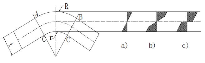
The material undergoes bending deformation under the action of forming, and the deformation zone is mainly concentrated in the abc region of the following figure. The metal is subjected to tensile and stress effects, and the process can be divided into an elastic deformation stage and a plastic deformation stage.
Elastic deformation stage: In the initial stage of forming, the bending force is not large, and the inner and outer layers of the material are elastically deformed by the tensile stress without reaching the yield limit (Fig. a).
Plastic deformation stage: As the bending force continues to increase, the radius of curvature of the material decreases. The inner and outer layers of the material enter the plastic deformation stage from the elastic deformation stage. Then, the plastic deformation zone gradually expands and deforms from the inner and outer layers of the material to the center of the thickness of the material, and transitions from elastic deformation to plastic deformation (Fig. bc).
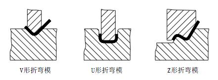
(1) commonly used bending mold
In order to extend the life of the mold, the part is designed to use rounded corners as much as possible.
(2) Bending radius
During the bending process, the inner layer is compressed and the outer layer is stretched. If the R angle is too large or too small, it is not appropriate. If it is too large, it will rebound. If it is too small, it will break. With the continuous improvement of the bending process, many manufacturers can now achieve zero R angle.
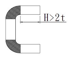
(3) Bending straight edge height
When bending 90 ̊ angle, the straight edge height H>2t outside the rounded corner area of the bend can guarantee its quality.
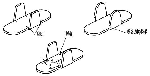
(4) Avoid bending on the oblique side
Prevents cracks or deformities when the side (trapezoidal) bends. The design should reserve grooves or change the roots to ladder shape. The groove width K ≥ 2t, the groove depth L ≥ t + R + K / 2.
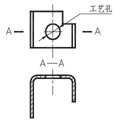
(5) U-shaped bend
In the U-bending member, the two curved sides are preferably equal in length so as not to shift to one side when bending. If not allowed, a process positioning hole can be set.
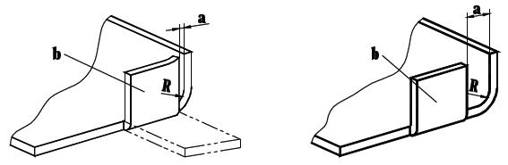
(6) ensure adequate arc space
When a<R, after bending, there is still a residual arc on the b-plane by a, In order to avoid the residual arc, a≥R must be made.
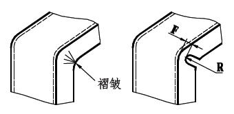
(7) Reserved incision
In order to prevent the rounded corners from being pressed during bending to produce wrinkles after extrusion, a reserved cut should be designed.
D) punching
(1) Minimum pitching diameter and minimum square hole edge length
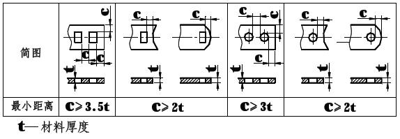
(2) hole spacing, hole margin, hole to bend distance
The above distance is usually taken as C≥3t
(3) Punching gap principle
Punching the notch should avoid sharp corners as much as possible. The sharp corner form is easy to shorten the service life of the mold, and cracks are easily formed at the sharp corners. Therefore, the product design as much as possible add rounded corners.
(4) Cantilever or slot structure / protruding or concave part
The shape of the blanking part should be as simple as possible to avoid excessively long cantilever slots on the blanking part.
For general steel A ≥ 1.5t, for alloy steel A ≥ 2t, for brass or aluminum A ≥ 1.2t.
(5) Common self-tapping screw bottom hole, flange hole diameter and flange height
(5) Calculation of punching pressure
F=L t S*1.3
F=Cutting pressure
L=Shear plane border
t=Material thickness
S=Shearing strength of by the punching shear material (kgf/mm²)
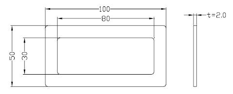
EG: If the material is SPCC, the shear strength of the sheet is 35 kgf/mm², and the minimum shear force is:
F=L t S*1.3=[(100+50)*2+(80+30)*2]*2.0*35*1.3=47320 kgf
(6) Punching section and burr
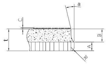
(1) Punching section
After the plate is cut by the die, the cross section will have two states: smooth shearing surface (bright band) and shear tearing section (section band).
In the technical requirements, the general drawings rarely specify the requirements for punching the cut surface. Very few precision parts will specify the scope of Bright band.
T - material thickness
A - smooth cutting face (bright band)
B - tears face ( section belt)
R - tears radius
a - section angle
C - burr height
(2) Deburring
Pay attention to the direction of the burr and avoid hurting people. The burrs can be removed by the Shooting process during processing.
(3) Burr height
If the design does not specify a tailoring requirement, it is usually controlled by the following height.
Copper/Aluminum: ≤12%t
Iron material: ≤10%t
Stainless steel: ≤8% t
(9) Connection of stamping parts
(1) Welding
Spot welding (resistance welding), arc welding, gas shielded welding (CO2, Ar), laser welding, gas welding, etc.
(2) rivet nuts
Common types of rivet nuts are Pressure riveted nut column, Pressure riveting nut, Pull rivet nut, Riveting nut, Floating riveting nut.
The main factors affecting the quality of riveting are: substrate properties, bottom hole size, riveting method.
Therefore, pay attention to the following when using rivet nuts:
a) Do not install steel or stainless steel riveted fasteners prior to anodizing or surface treatment of the aluminum sheet.
b) There is too much pressure on the same straight line. The extruded material has no place to flow and will generate a great deal of stress to bend the workpiece into an arc.
c) Try to ensure that the surface of the metal plate is plated and then installed with riveted fasteners.
d) M5, M6, M8, M10 nuts are usually spot welded. Too large nuts generally require higher strength and arc welding can be used. M4 (including M4) follows as much as possible with rivet nuts. If it is a plating part, unscrewed rivet nuts can be used.
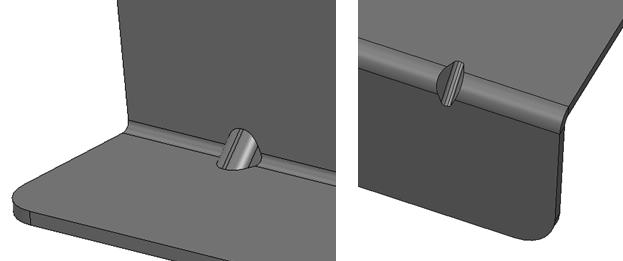
e) When the nut is riveted on the bending edge, in order to ensure the riveting quality of the riveting nut, It should be noted that the distance from the rivet hole edge to the bending edge must be greater than the bending deformation area; The distance L from the center of the riveted nut to the inner side of the folded edge should be greater than the sum of the outer cylindrical radius of the riveted nut and the inner radius of the bend, that is, L>D/2+r.
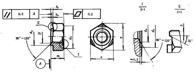
(3) Projection Weld Nuts / Spot Weld Nuts
The projection nut (spot weld nut) is widely used in the design of sheet metal parts. It is recommended to use the welding hex nut GB/T 13681-92, which has a self-aligning structure when welding.
(1) Material selection
According to the thickness, strength, elasticity requirements, choose the right material for different applications.
(2) The layout of stamping parts
Optimize the design, rationalize the layout, and strive for the adoption of waste-free or less-scrap arrangements.
(3) Shape of stamping
In the case of meeting product requirements, it should be as simple and symmetrical as possible to minimize waste.
(b) Part thickness and strengthening rib
(1) Thickness
In order to ensure the life of the mold, the quality of the product and the ordering of materials on the market, the thickness of the stamped material should take the following range:
Iron/stainless steel: 0.1≤t≤3 (mm)
Copper/aluminum: 0.1≤t≤4 (mm)
(2) Strengthening rib
For larger or longer sheet metal parts, the strengthening rib should be properly designed to increase its strength.
In addition, bends are made at the bent corners of the bent parts. Can play a strengthening role of ribs.
(c) Bending
Bending is a forming method that relies on material flow rather than material separation, using bending to change the angle or shape. Most of the parts that need to be formed can be realized by a mold on a common press, or can be formed by special equipment such as a bending machine.
The material undergoes bending deformation under the action of forming, and the deformation zone is mainly concentrated in the abc region of the following figure. The metal is subjected to tensile and stress effects, and the process can be divided into an elastic deformation stage and a plastic deformation stage.
Elastic deformation stage: In the initial stage of forming, the bending force is not large, and the inner and outer layers of the material are elastically deformed by the tensile stress without reaching the yield limit (Fig. a).
Plastic deformation stage: As the bending force continues to increase, the radius of curvature of the material decreases. The inner and outer layers of the material enter the plastic deformation stage from the elastic deformation stage. Then, the plastic deformation zone gradually expands and deforms from the inner and outer layers of the material to the center of the thickness of the material, and transitions from elastic deformation to plastic deformation (Fig. bc).
(1) commonly used bending mold
In order to extend the life of the mold, the part is designed to use rounded corners as much as possible.
(2) Bending radius
During the bending process, the inner layer is compressed and the outer layer is stretched. If the R angle is too large or too small, it is not appropriate. If it is too large, it will rebound. If it is too small, it will break. With the continuous improvement of the bending process, many manufacturers can now achieve zero R angle.
(3) Bending straight edge height
When bending 90 ̊ angle, the straight edge height H>2t outside the rounded corner area of the bend can guarantee its quality.
(4) Avoid bending on the oblique side
Prevents cracks or deformities when the side (trapezoidal) bends. The design should reserve grooves or change the roots to ladder shape. The groove width K ≥ 2t, the groove depth L ≥ t + R + K / 2.
(5) U-shaped bend
In the U-bending member, the two curved sides are preferably equal in length so as not to shift to one side when bending. If not allowed, a process positioning hole can be set.
(6) ensure adequate arc space
When a<R, after bending, there is still a residual arc on the b-plane by a, In order to avoid the residual arc, a≥R must be made.
(7) Reserved incision
In order to prevent the rounded corners from being pressed during bending to produce wrinkles after extrusion, a reserved cut should be designed.
D) punching
(1) Minimum pitching diameter and minimum square hole edge length
(2) hole spacing, hole margin, hole to bend distance
The above distance is usually taken as C≥3t
(3) Punching gap principle
Punching the notch should avoid sharp corners as much as possible. The sharp corner form is easy to shorten the service life of the mold, and cracks are easily formed at the sharp corners. Therefore, the product design as much as possible add rounded corners.
(4) Cantilever or slot structure / protruding or concave part
The shape of the blanking part should be as simple as possible to avoid excessively long cantilever slots on the blanking part.
For general steel A ≥ 1.5t, for alloy steel A ≥ 2t, for brass or aluminum A ≥ 1.2t.
(5) Common self-tapping screw bottom hole, flange hole diameter and flange height
(5) Calculation of punching pressure
F=L t S*1.3
F=Cutting pressure
L=Shear plane border
t=Material thickness
S=Shearing strength of by the punching shear material (kgf/mm²)
EG: If the material is SPCC, the shear strength of the sheet is 35 kgf/mm², and the minimum shear force is:
F=L t S*1.3=[(100+50)*2+(80+30)*2]*2.0*35*1.3=47320 kgf
(6) Punching section and burr
(1) Punching section
After the plate is cut by the die, the cross section will have two states: smooth shearing surface (bright band) and shear tearing section (section band).
In the technical requirements, the general drawings rarely specify the requirements for punching the cut surface. Very few precision parts will specify the scope of Bright band.
T - material thickness
A - smooth cutting face (bright band)
B - tears face ( section belt)
R - tears radius
a - section angle
C - burr height
(2) Deburring
Pay attention to the direction of the burr and avoid hurting people. The burrs can be removed by the Shooting process during processing.
(3) Burr height
If the design does not specify a tailoring requirement, it is usually controlled by the following height.
Copper/Aluminum: ≤12%t
Iron material: ≤10%t
Stainless steel: ≤8% t
(9) Connection of stamping parts
(1) Welding
Spot welding (resistance welding), arc welding, gas shielded welding (CO2, Ar), laser welding, gas welding, etc.
(2) rivet nuts
Common types of rivet nuts are Pressure riveted nut column, Pressure riveting nut, Pull rivet nut, Riveting nut, Floating riveting nut.
The main factors affecting the quality of riveting are: substrate properties, bottom hole size, riveting method.
Therefore, pay attention to the following when using rivet nuts:
a) Do not install steel or stainless steel riveted fasteners prior to anodizing or surface treatment of the aluminum sheet.
b) There is too much pressure on the same straight line. The extruded material has no place to flow and will generate a great deal of stress to bend the workpiece into an arc.
c) Try to ensure that the surface of the metal plate is plated and then installed with riveted fasteners.
d) M5, M6, M8, M10 nuts are usually spot welded. Too large nuts generally require higher strength and arc welding can be used. M4 (including M4) follows as much as possible with rivet nuts. If it is a plating part, unscrewed rivet nuts can be used.
e) When the nut is riveted on the bending edge, in order to ensure the riveting quality of the riveting nut, It should be noted that the distance from the rivet hole edge to the bending edge must be greater than the bending deformation area; The distance L from the center of the riveted nut to the inner side of the folded edge should be greater than the sum of the outer cylindrical radius of the riveted nut and the inner radius of the bend, that is, L>D/2+r.
(3) Projection Weld Nuts / Spot Weld Nuts
The projection nut (spot weld nut) is widely used in the design of sheet metal parts. It is recommended to use the welding hex nut GB/T 13681-92, which has a self-aligning structure when welding.


