Metal Stamping Parts Mold Design And Production
Chapter One Parts Introduction
Parts analysis description1. Parts shape and general requirements
As shown in Figure 1-1, the material is stainless steel, the material thickness is 0.5mm, and the dimensional accuracy of the workpiece must meet the requirements of the drawings. Unmarked accuracy according to IT12 level, The production program has an annual output of 100,000 pieces.
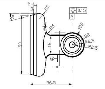
Figure 1-1
Chapter two Process analysis of parts
1. Process analysis of partsThe shape of the workpiece is simple, the size and thickness are moderate, and it is generally mass-produced. It belongs to ordinary stamping parts, but pay attention to the following points when designing cold stamping dies:
2. The outline and structure of the parts are simple, but it is necessary to consider the processing of several holes.
A, the position requirements of the two 2 holes,
B, due to assembly,
C, two holes must have a certain same
D, shafting requirements,
E, its value is 0.15mm.
3. The processing difficulty of this part is mainly the positioning of the center distance of the hole 2.
Since several holes have a small diameter and a certain batch size, the design of the material and structure of the mold should be emphasized to ensure a certain mold life.
Second, the determination of the process plan
According to the analysis of the process of the workpiece, the basic processes include blanking, punching and bending. There are several types of processing schemes and their reasonable processing schemes in the following order:
1. Blanking-punching-bending, single process stamping.
2, blanking - bending - punching, single process stamping.
3, blanking punching - bending ribs, composite stamping.
Scheme 1) It is a single-step stamping die.
Since this part has a certain production batch, too many processes, and reduces the precision of the product, and the production efficiency of this scheme is not suitable for mass production, it is not suitable to adopt this scheme.
Scheme 2) It is also a single-step stamping die.
In addition to the fault of the scheme 1, it is difficult to ensure the positional accuracy of the hole, and the lack of positioning accuracy in the bending is difficult to ensure, so it is not suitable to adopt this scheme.
Scheme 3) Composite stamping die.
Due to the structure of the part, the thickness of the material is thin, and punching and blanking are completed once. Therefore, it is best to adopt this scheme.
The specific plan is as follows:
Third, the determination of process parameters
1. Calculation of blank size
Calculation of the length of the external dimensions
The relative bending radius of the part is:
R/t=2/0.5=4>0.5
Where R bending radius;
T material thickness.
Seen, parts belonging to the large bending radius member, should now seek the neutral bending deformation zone Curvature radius ρ.
Formula for calculating the neutral position of the textbook p145
ρ=R+Xt
Where X is the strain-neutral layer displacement coefficient determined by experiment
From the textbook p145 Table 4-5 find X take 0.42
and so:
ρ=R+Xt
=2+0.42×0.5
=2.21mm
L=∑L straight +∑L bend
L bend = [(180-a) / 180] * πρ
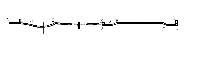
Therefore, the length of the part is as shown in Figure 2-2.
L=LAB+LBC+LCD+LDE+LEF+LFG+LGH+LHI+LIJ+LJK+LKL
L=3+3.0342+8.54+14+1+1+1.8028+13+1.8028+1+2
L=50.1798
The DE segment belongs to the process setting. The purpose is to reduce the bending springback. The radius is large and can be regarded as a straight line, so the length of the DE segment is calculated as a straight line.
1. The width of the contour is calculated:
Due to the consideration of the utilization of the sheet material and the convenience of the layout, the process size of the workpiece generated by CAD is: the outline width is L=53.74mm
2. Calculation of layout size
Determination of the edge value:
From the textbook P46 Table 3-14, the value of a1 between workpieces with L>50 is found to be 2.2*0.8=1.76.
The value of the side a is 2.5*0.8=2
3. calculates the width of the material
In the design of the mold is for convenience, the strip width calculation formula using the non-side pressure device feeding method is as follows:
B=(D+2a +Z) 0-δ
Formula
B——the basic size of the strip width;
D——the maximum size of the part profile in the strip width direction
a - side edge
Z——the gap between the guide plate and the widest strip
Δ——the negative deviation of the strip width
The margin a is as shown above
Gap δ, shear tolerance Z check the textbook p47 Table 3-17 found δ = 0.5mm, Z = 0.5mm
Calculated by the above formula B = (53.74 + 2 * 2 + 0.5 > 0 - 0.5 = 56.240 - 0.5mm
Calculation step distanceL=LAB+LBC+LCD+LDE+LEF+LFG+LGH+LHI+LIJ+LJK+LKL
L=3+3.0342+8.54+14+1+1+1.8028+13+1.8028+1+2
L=50.1798
The DE segment belongs to the process setting. The purpose is to reduce the bending springback. The radius is large and can be regarded as a straight line, so the length of the DE segment is calculated as a straight line.
1. The width of the contour is calculated:
Due to the consideration of the utilization of the sheet material and the convenience of the layout, the process size of the workpiece generated by CAD is: the outline width is L=53.74mm
2. Calculation of layout size
Determination of the edge value:
From the textbook P46 Table 3-14, the value of a1 between workpieces with L>50 is found to be 2.2*0.8=1.76.
The value of the side a is 2.5*0.8=2
3. calculates the width of the material
In the design of the mold is for convenience, the strip width calculation formula using the non-side pressure device feeding method is as follows:
B=(D+2a +Z) 0-δ
Formula
B——the basic size of the strip width;
D——the maximum size of the part profile in the strip width direction
a - side edge
Z——the gap between the guide plate and the widest strip
Δ——the negative deviation of the strip width
The margin a is as shown above
Gap δ, shear tolerance Z check the textbook p47 Table 3-17 found δ = 0.5mm, Z = 0.5mm
Calculated by the above formula B = (53.74 + 2 * 2 + 0.5 > 0 - 0.5 = 56.240 - 0.5mm
Unfolded view of the part (see Figure 2-3 on the right)
The generated effective lateral dimension Ls = 53.74mm
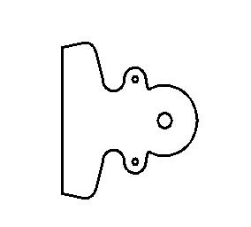
Figure 2-3
The step spacing calculation formula is:L=Ls+a1
Where L is the step spacing
Ls - is the horizontal effective size
A1 - margin
L=53.74+2=55.74mm
Whereby the mold can be obtained nesting is as follows:
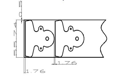
Figure 2-4
3 Calculate material utilization
By textbook p43 style 3-19
η=nA/BL×100%
η - for material utilization;
A——the actual area of the blanking part within one step;
B - the width of the strip
L - the length of the strip
n - the total number of blanks on a sheet
η=28*1932.765/(56*1500)=65%


