The Front Support Member Press-Punching Process Design Of Motorcycle Side Cover (Flexural Modulus)
Figure 12-1 shows: Schematic diagram of the front support parts sof the motorcycle side cover, Material Q215 steel, Thickness 1.5mm. The annual production capacity is 500,000 pieces, and the stamping process plan is required.
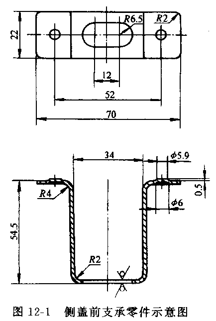
Figure 12-1 Side cover front support parts schematic
1. Parts and their stamping process analysis
The front support part of the motorcycle side cover is positioned by a 2 mm convex hull and welded on the electrical component bracket of the frame. The waist round hole is used for the assembly of the side cover, so the position of the waist hole is the key point of the part to be guaranteed. In addition, the part is a concealed part, which is completely shielded by the side cover, and the appearance is not high, and only needs to be flat.
The four corners of the end of the part are sharp corners. If the blanking process is adopted, the craftability is poor. According to the assembly and use of the part, in order to improve the processability of the blanking, the four corners are modified into rounded corners, and the radius of the fillet is 2 mm. In addition, the "legs" of the parts are long, and if the bending and the correction of the bending are effectively utilized to control the rebound, the parts with more accurate shapes and sizes can be obtained.
The distance from the waist hole edge to the center of the bending radius R is 2.5 mm. It is larger than the material thickness (1.5mm), so that the round hole is outside the deformation zone, and does not cause the hole to deform when bent, so the hole can be punched out before bending.
2. Determine the process plan
First, the type of stamping process and the order of selecting the process are determined according to the shape of the part. The basic processes required to punch the part are shearing (or blanking), punching, rounding, primary bending, secondary bending, and punching. The bending determines the overall shape and size of the part, so it is important to choose a reasonable bending method.
(1) Methods and comparison of bending deformation
The method of bending and deforming the part may be any one as shown in Fig. 12-2.
The first method (Fig. 12-2a) is a one-shot molding, which has the advantage of forming with a pair of molds, which can increase productivity and reduce equipment and operators. The disadvantage is that the entire area of the blank is almost involved in the intense deformation, the surface of the part is severely scratched, and the area of the scratch is large, the shape and size of the part are not accurate, and the bending is thin.
These defects will increase with the length of the "legs" of the part. The reduction in the length of the "legs" becomes more apparent.
The second method (Fig. 12-2b) is to first bend the ends of the two corners with a pair of molds and then bend the middle corners of the other pair of molds. This is obviously much more moderate than the first method of bending deformation, but the rebound phenomenon is difficult to control, and the mold, equipment and operators are added.
The third method (Fig. 12-2c) is to first bend the two corners of a pair of molds and pre-bend the middle corners by 45°, and then bend them on the other mold.
In this way, since the rebound can be controlled by over-bending and correcting the bending, the shape and size of the part are highly accurate. In addition, the surface quality of the parts is better due to the less resistance of the material to the convex and concave corners during the forming process. This method of bending deformation is particularly advantageous for the formation of high precision or long "foot" short "foot" bends.
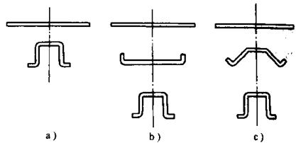
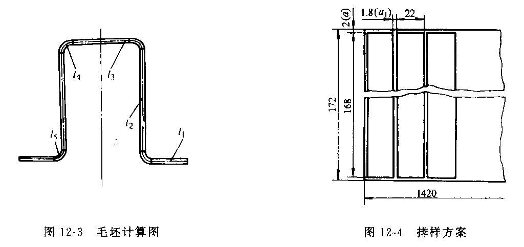
Figure 12-3 Blank calculation chart Figure 12-4 Product layout plan
Figure 12-1 Side cover front support parts schematic
1. Parts and their stamping process analysis
The front support part of the motorcycle side cover is positioned by a 2 mm convex hull and welded on the electrical component bracket of the frame. The waist round hole is used for the assembly of the side cover, so the position of the waist hole is the key point of the part to be guaranteed. In addition, the part is a concealed part, which is completely shielded by the side cover, and the appearance is not high, and only needs to be flat.
The four corners of the end of the part are sharp corners. If the blanking process is adopted, the craftability is poor. According to the assembly and use of the part, in order to improve the processability of the blanking, the four corners are modified into rounded corners, and the radius of the fillet is 2 mm. In addition, the "legs" of the parts are long, and if the bending and the correction of the bending are effectively utilized to control the rebound, the parts with more accurate shapes and sizes can be obtained.
The distance from the waist hole edge to the center of the bending radius R is 2.5 mm. It is larger than the material thickness (1.5mm), so that the round hole is outside the deformation zone, and does not cause the hole to deform when bent, so the hole can be punched out before bending.
2. Determine the process plan
First, the type of stamping process and the order of selecting the process are determined according to the shape of the part. The basic processes required to punch the part are shearing (or blanking), punching, rounding, primary bending, secondary bending, and punching. The bending determines the overall shape and size of the part, so it is important to choose a reasonable bending method.
(1) Methods and comparison of bending deformation
The method of bending and deforming the part may be any one as shown in Fig. 12-2.
The first method (Fig. 12-2a) is a one-shot molding, which has the advantage of forming with a pair of molds, which can increase productivity and reduce equipment and operators. The disadvantage is that the entire area of the blank is almost involved in the intense deformation, the surface of the part is severely scratched, and the area of the scratch is large, the shape and size of the part are not accurate, and the bending is thin.
These defects will increase with the length of the "legs" of the part. The reduction in the length of the "legs" becomes more apparent.
The second method (Fig. 12-2b) is to first bend the ends of the two corners with a pair of molds and then bend the middle corners of the other pair of molds. This is obviously much more moderate than the first method of bending deformation, but the rebound phenomenon is difficult to control, and the mold, equipment and operators are added.
The third method (Fig. 12-2c) is to first bend the two corners of a pair of molds and pre-bend the middle corners by 45°, and then bend them on the other mold.
In this way, since the rebound can be controlled by over-bending and correcting the bending, the shape and size of the part are highly accurate. In addition, the surface quality of the parts is better due to the less resistance of the material to the convex and concave corners during the forming process. This method of bending deformation is particularly advantageous for the formation of high precision or long "foot" short "foot" bends.
Figure 12-2 Bending
a) a pair of mold forming b), c) two pairs of mold forming
a) a pair of mold forming b), c) two pairs of mold forming
(2) Process combination plan and comparison
The following various combinations can be made according to the basic procedures required for stamping the part and the different methods of bending forming.
Option 1: Finishing and punching round hole composite, curved four corners, punch convex hull. The advantage is that the process is relatively concentrated, occupying less equipment and personnel, but the rebound is difficult to control, the size and shape are not accurate, and the surface scratches are serious.
Option 2: blanking and punching round hole composite, curved end two corners, curved middle two corners, punch convex hull.
The advantage is that the mold structure is simple and the production is fast, but the rebound is difficult to control, the size and shape are not accurate, and the process is dispersed, occupying a large number of equipment and personnel.
The following various combinations can be made according to the basic procedures required for stamping the part and the different methods of bending forming.
Option 1: Finishing and punching round hole composite, curved four corners, punch convex hull. The advantage is that the process is relatively concentrated, occupying less equipment and personnel, but the rebound is difficult to control, the size and shape are not accurate, and the surface scratches are serious.
Option 2: blanking and punching round hole composite, curved end two corners, curved middle two corners, punch convex hull. The advantage is that the mold structure is simple and the production is fast, but the rebound is difficult to control, the size and shape are not accurate, and the process is dispersed, occupying a large number of equipment and personnel.
Option 3: The blanking and punching round holes are composited, the two ends of the curved end are bent, and the middle two corners are pre-bent 45°, the middle two corners are bent, and the convex convex hull is bent. The advantage is that the workpiece rebound is easy to control, the size and shape are accurate, and the surface quality is good, which is particularly advantageous for the formation of such long "leg" short "foot" bending parts, the disadvantage is that the process is dispersed, occupying a large number of equipment and personnel.
Option 4: Punching the round hole, cutting and bending the four corners continuously punching and punching the convex hull. The advantage is that the process is relatively concentrated, occupying less equipment and personnel, but the rebound is difficult to control, the size and shape are not accurate, and the surface scratches are serious.
Option 5: Punch the round hole, cut and bend the end to punch the round hole, cut the continuous punching, bend the middle two corners, punch the convex hull. This kind of scheme is basically the same as that of the second scheme. It only uses a continuous mold with complicated structure, so the workpiece rebound is difficult to control, and the size and shape are not accurate.
Option 6: The whole process of the third scheme is combined, and the strip is continuously punched. The advantage is that the process is concentrated, and only one pair of molds is used to complete all the processes. The essence is that the various steps of the third scheme are respectively arranged in the respective positions of the continuous mold, so that the advantages of the third scheme are also obtained, and the disadvantage is that the mold structure is complicated, and the installation, debugging and maintenance are difficult. The manufacturing cycle is long.
The following various combinations can be made according to the basic procedures required for stamping the part and the different methods of bending forming.
Option 1: Finishing and punching round hole composite, curved four corners, punch convex hull. The advantage is that the process is relatively concentrated, occupying less equipment and personnel, but the rebound is difficult to control, the size and shape are not accurate, and the surface scratches are serious.
Option 2: blanking and punching round hole composite, curved end two corners, curved middle two corners, punch convex hull.
The advantage is that the mold structure is simple and the production is fast, but the rebound is difficult to control, the size and shape are not accurate, and the process is dispersed, occupying a large number of equipment and personnel.
The following various combinations can be made according to the basic procedures required for stamping the part and the different methods of bending forming.
Option 1: Finishing and punching round hole composite, curved four corners, punch convex hull. The advantage is that the process is relatively concentrated, occupying less equipment and personnel, but the rebound is difficult to control, the size and shape are not accurate, and the surface scratches are serious.
Option 2: blanking and punching round hole composite, curved end two corners, curved middle two corners, punch convex hull. The advantage is that the mold structure is simple and the production is fast, but the rebound is difficult to control, the size and shape are not accurate, and the process is dispersed, occupying a large number of equipment and personnel.
Option 3: The blanking and punching round holes are composited, the two ends of the curved end are bent, and the middle two corners are pre-bent 45°, the middle two corners are bent, and the convex convex hull is bent. The advantage is that the workpiece rebound is easy to control, the size and shape are accurate, and the surface quality is good, which is particularly advantageous for the formation of such long "leg" short "foot" bending parts, the disadvantage is that the process is dispersed, occupying a large number of equipment and personnel.
Option 4: Punching the round hole, cutting and bending the four corners continuously punching and punching the convex hull. The advantage is that the process is relatively concentrated, occupying less equipment and personnel, but the rebound is difficult to control, the size and shape are not accurate, and the surface scratches are serious.
Option 5: Punch the round hole, cut and bend the end to punch the round hole, cut the continuous punching, bend the middle two corners, punch the convex hull. This kind of scheme is basically the same as that of the second scheme. It only uses a continuous mold with complicated structure, so the workpiece rebound is difficult to control, and the size and shape are not accurate.
Option 6: The whole process of the third scheme is combined, and the strip is continuously punched. The advantage is that the process is concentrated, and only one pair of molds is used to complete all the processes. The essence is that the various steps of the third scheme are respectively arranged in the respective positions of the continuous mold, so that the advantages of the third scheme are also obtained, and the disadvantage is that the mold structure is complicated, and the installation, debugging and maintenance are difficult. The manufacturing cycle is long.
In summary, although the part does not require a high surface appearance, since the "leg" is particularly long, it is necessary to effectively use the over-bending and correction to control the rebound. Both schemes 3 and 6 can meet this requirement, but considering that the production volume of the parts is not too large, option 3 is selected, and the stamping process is as follows:
Blanking punching, one-bend shape (two corners at the end of the bend and pre-bend 45° in the middle), secondary bending (two corners in the middle), punching convex hull.
3. Calculation of main process parameters
(1) Blank unfolding size (check the book) The expanded size is calculated according to the figure in Figure 12.3.
Blank expansion length

Formula: L1 = 12.5mm; L2 = 45.5m; L3 = 30mm; L4 and L5 are calculated.
Wherein the circle radius r = 2mm and 4mm, the material thickness t = 1.5mm, neutral layer x by the coefficient r / t check taken from Table 3-2. When r=2mm, take x=0.43, and when r=4mm, take x=0.46.
Substituting the above values into the above formula

Considering that the material is slightly elongated when bent, the blank unfolding length L = 168 mm.
For curved parts with high precision requirements, it is also necessary to correct them after trial bending to obtain accurate unfolding dimensions.
(2) Determining the layout plan and calculating the material utilization rate
1) Determine the layout plan and select a reasonable layout plan according to the shape of the part to improve material utilization. The part adopts blanking and punching combined punching, the shape of the blank is rectangular, and the length direction is large. In order to facilitate feeding, a single row scheme is adopted (see Figure 12-4). The edge values a and a1 were found in Table 2-12, and a = 2 mm, a1 = 1.8 mm.
Blanking punching, one-bend shape (two corners at the end of the bend and pre-bend 45° in the middle), secondary bending (two corners in the middle), punching convex hull.
3. Calculation of main process parameters
(1) Blank unfolding size (check the book) The expanded size is calculated according to the figure in Figure 12.3.
Blank expansion length
Formula: L1 = 12.5mm; L2 = 45.5m; L3 = 30mm; L4 and L5 are
calculated.Wherein the circle radius r = 2mm and 4mm, the material thickness t = 1.5mm, neutral layer x by the coefficient r / t check taken from Table 3-2. When r=2mm, take x=0.43, and when r=4mm, take x=0.46.
Substituting the above values into the above formula
Considering that the material is slightly elongated when bent, the blank unfolding length L = 168 mm.
For curved parts with high precision requirements, it is also necessary to correct them after trial bending to obtain accurate unfolding dimensions.
(2) Determining the layout plan and calculating the material utilization rate
1) Determine the layout plan and select a reasonable layout plan according to the shape of the part to improve material utilization. The part adopts blanking and punching combined punching, the shape of the blank is rectangular, and the length direction is large. In order to facilitate feeding, a single row scheme is adopted (see Figure 12-4). The edge values a and a1 were found in Table 2-12, and a = 2 mm, a1 = 1.8 mm.
Figure 12-3 Blank calculation chart Figure 12-4 Product layout plan
2) Determine the specification and cutting method of the metal sheet. According to the width dimension of the strip, select the appropriate metal sheet size so that the remaining side material is as small as possible. The width of the part is 172 mm, and it is preferable to select a metal sheet of 1.5 mm × 710 mm × 1420 mm.
The method of cutting should consider the specification of the selected metal sheet, the number of punched parts, and the convenience of the cutting operation. The part is suitable for vertical cutting. For larger parts, the number of parts to be punched is considered to reduce the material cost of the part.
(3) Calculate the material consumption process quota and material utilization rate. According to the layout calculation, the number of parts that can be punched by one steel plate is n=4×59=236 (piece).
Material consumption process quota

Material utilization

The method of cutting should consider the specification of the selected metal sheet, the number of punched parts, and the convenience of the cutting operation. The part is suitable for vertical cutting. For larger parts, the number of parts to be punched is considered to reduce the material cost of the part.
(3) Calculate the material consumption process quota and material utilization rate. According to the layout calculation, the number of parts that can be punched by one steel plate is n=4×59=236 (piece).
Material consumption process quota
Material utilization
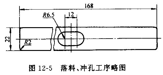
The area of the part is calculated from Figure 12-5:
4. Determination of mold structure form
The structural forms of blanking punching die, primary bending die, secondary bending die and punching convex die are shown in Figure 12-6, Figure 12-7, Figure 12-8 and Figure 12-9, respectively.
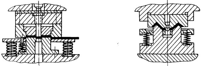
Figure 12-6 blanking die punch structure Figure 12-7 One-time curved mold structure
4. Determination of mold structure form
The structural forms of blanking punching die, primary bending die, secondary bending die and punching convex die are shown in Figure 12-6, Figure 12-7, Figure 12-8 and Figure 12-9, respectively.
Figure 12-6 blanking die punch structure Figure 12-7 One-time curved mold structure


