Machining Process of Precision Titanium Alloy Gear Parts
Key words: Titanium alloy gear parts, machined gear parts, gear processing, tooth profile processing, tooth end processing, tooth surface heat treatment, precision benchmark correction and tooth profile finishing.
Figure 9-17 shows a double gear, the material is TC4 Ti-6Al-4V, the accuracy is 7-6-6, the processing process is shown in Table 9-6.
As can be seen from the table, the gear processing process generally goes through the following stages: Blank heat treatment, tooth blank machining, tooth profile machining, tooth end machining, tooth surface heat treatment, fine reference correction and tooth finishing.
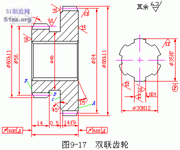
Figure 9-17 Titanium alloy double gear
two. Main Processing Surfaces of Gears
1. The main machining surface of the gear has a tooth surface and a gear reference surface. The latter includes a reference hole with a perforated gear, a mounting end face for the cutting process, and a crest cylindrical surface for use as a measurement reference for aligning the position of the blank or measuring the tooth thickness.
2. Gear material and blank
Commonly used gear materials are carbon structural steels such as TC4 Ti-6Al-4V, 15 steel, and 45 steel; Gears with high speed, high force and high precision are commonly used in alloy structural steels such as 20Cr, 40Cr, 38CrMoAl, 20CrMnTiA, Ti etc.
The blank of the gear is determined by factors such as the material, structural shape, size, use conditions and production batch of the gear. Titanium alloy, bar stock, forged blank, cast steel or cast iron blank are commonly used.
Three. The main technical requirements of spur gears,
1. Gear accuracy and backlash
GBl0095 "Involute Cylindrical Gear Accuracy" specifies 12 precision grades for gears and gear pairs.
Among them, grades 1 to 2 are super-precision grades;
Levels 3-5 are high precision grades;
Levels 6-8 are medium precision grades;
Grades 9-12 are low precision grades.
Grade 7 is the most commonly used in gear cutting process and machinery. According to the characteristics of the gear errors and their main influence on the transmission performance, the gear tolerances and limit deviations are divided into three tolerance groups (Table 13-4). Depending on the gear usage requirements, different tolerance levels can be used for each tolerance group.
The backlash of gear pair refers to the distance between two non-working tooth surfaces along the normal direction (i.e. the normal backlash) when the gear pair engages, and the backlash is used to ensure the normal work of the gear pair. When machining gears, the limit deviation of the tooth thickness is used to control and ensure the size of the gear side clearance.
2. Gear reference surface accuracy
The dimensional error and shape position error of the gear reference surface directly affect the accuracy of the gear and gear pair. Therefore, the tolerance of the blank is specified in the Appendix of GBl0095. For gears with a precision class of 6 to 8, the dimensional tolerance and shape tolerance of the perforated gear reference hole is IT6-IT7, and the toroidal circle diameter tolerance used as the measurement reference is IT8; For gears with Accuracy grades of 6 to 8, the dimension tolerance and shape tolerance of the reference hole of the gears with holes are IT6-IT7, and the diameter tolerance of the top circle used as the measuring reference is IT8. The radial and end face circular runout tolerances of the reference plane are between 11 and 22 μm (medium and small gears with an index circle diameter of not more than 400 mm).
3. Surface roughness
The surface roughness of the gear tooth surface and the tooth blank reference surface has a certain influence on the life of the gear and the noise in the transmission.
For gears with 6 to 8 precision, the surface roughness Ra of the tooth surface is generally 0.8-3.2 μm. The reference hole is 0.8-1.6 μm. The reference journal is 0.4-1.6μm. The reference end face is 1.6 to 3.2 μm. The cylindrical top surface of the tooth is 3.2 μm.
Third, the main process problems of spur gear machining
1. Positioning benchmark
The selection of the gear machining positioning reference should conform to the principle of reference coincidence, and be as consistent as possible with the assembly reference and measurement basis. At the same time, in the whole process of gear processing (such as hobbing, shaving, honing, etc.), the same positioning datum should be selected to maintain the unification of datum.
For the ring gear of the perforated gear or the assembled gear, a special mandrel is often used to position the inner bore and the end face of the tooth blank. This method has high positioning accuracy and high productivity, and is suitable for mass production. In the case of single-piece small batch production, the outer circle and the end face are often used as the positioning reference to eliminate the mandrel, but the outer circle is required to have a small radial runout of the hole, and the method has low productivity.
2. Gear blank processing
The processing of gear blank mainly includes hole and end face of gear with hole.
(1) The main schemes of tooth blank hole processing are as follows:
1) Drilling, reaming, reaming and keyway insertion
2) Drilling, reaming, pulling keyway and grinding hole
3) One pull or insert keyway-grinding hole for turning or boring
(2) Turning is mainly used for the outer circle and end face of the billet.
In mass production, high productivity machine tools are often used to process tooth blanks, such as multi-axis, multi-station, multi-tool semi-automatic machine tools. In single-piece and small-batch production, general-purpose lathes are generally used, but it must be noted that the finishing of the inner hole and the reference end face should be completed in one installation and marked on the reference end face.
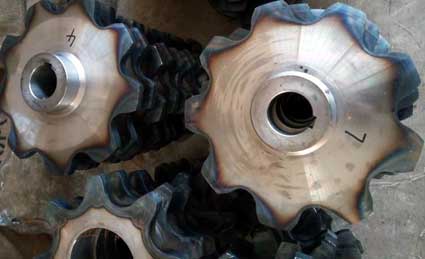
3. Selection of Cutting Method for Tooth Surface
The selection of gear surface cutting method mainly depends on gear accuracy grade, production batch, production conditions and heat treatment requirements.
Hobbing or gear shaping can be used to meet the requirements of 7-8 grade precision non-hardened gears.
Hobbing-shaving can be used to meet the requirements of 6-7 grade precision non-hardened gears.
Grade 6-7 precision hardened gears can be used when the production batch is small.
6-7 precision hardened gears when the production volume is small. Can be used: Hobbing-- (or pinion)-tooth surface heat treatment-grinding processing scheme, when the production batch is large, the hobbing-shaving-tooth surface heat treatment-crushing machining scheme can be adopted.
4. Cylindrical gear machining process
(1) Gears that require only heat treatment
Blank manufacturing - Blank heat treatment (normalizing) - rough processing of gear blank - quenching and tempering - finish processing of gear blank - rough processing of tooth surface - finish processing of tooth surface.
(2) Medium carbon structural steel and titanium alloy structural steel gears whose surface is to be quenched
Blank manufacturing - normalizing - roughing of tooth blanks - quenching and tempering - semi-finishing of tooth blanks - roughing of tooth surface (semi-finishing) - tooth surface quenching - tooth blank finishing - tooth surface finishing.
(3) gears whose teeth are to be carburized or nitrided
Blank manufacturing - normalizing - roughing of the blank - normalizing or quenching - semi-finishing of the blank - roughening of the tooth surface - semi-finishing of the tooth surface - carburizing quenching or nitriding - finishing of the tooth blank - tooth surface finishing .
Figure 9-17 shows a double gear, the material is TC4 Ti-6Al-4V, the accuracy is 7-6-6, the processing process is shown in Table 9-6.
As can be seen from the table, the gear processing process generally goes through the following stages: Blank heat treatment, tooth blank machining, tooth profile machining, tooth end machining, tooth surface heat treatment, fine reference correction and tooth finishing.

Figure 9-17 Titanium alloy double gear
| Tooth number | Ⅰ | Ⅱ | Tooth number | Ⅰ | Ⅱ |
| Modulus | 2 | 2 | Basal deviation | ±0.016 | ±0.016 |
| Number of teeth | 28 | 42 | Toothed tolerance | 0.017 | 0.018 |
| Accuracy level | 7GK | 7JL | Tooth direction tolerance | 0.017 | 0.017 |
| Public normal length variation | 0.039 | 0.024 | Average length of common normal | 21.36 0-0.05 | 27.6 0-0.05 |
| Ring gear radial runout | 0.050 | 0.042 | Across tooth number | 4 | 5 |

two. Main Processing Surfaces of Gears
1. The main machining surface of the gear has a tooth surface and a gear reference surface. The latter includes a reference hole with a perforated gear, a mounting end face for the cutting process, and a crest cylindrical surface for use as a measurement reference for aligning the position of the blank or measuring the tooth thickness.
2. Gear material and blank
Commonly used gear materials are carbon structural steels such as TC4 Ti-6Al-4V, 15 steel, and 45 steel; Gears with high speed, high force and high precision are commonly used in alloy structural steels such as 20Cr, 40Cr, 38CrMoAl, 20CrMnTiA, Ti etc.
The blank of the gear is determined by factors such as the material, structural shape, size, use conditions and production batch of the gear. Titanium alloy, bar stock, forged blank, cast steel or cast iron blank are commonly used.
Three. The main technical requirements of spur gears,
1. Gear accuracy and backlash
GBl0095 "Involute Cylindrical Gear Accuracy" specifies 12 precision grades for gears and gear pairs.
Among them, grades 1 to 2 are super-precision grades;
Levels 3-5 are high precision grades;
Levels 6-8 are medium precision grades;
Grades 9-12 are low precision grades.
Grade 7 is the most commonly used in gear cutting process and machinery. According to the characteristics of the gear errors and their main influence on the transmission performance, the gear tolerances and limit deviations are divided into three tolerance groups (Table 13-4). Depending on the gear usage requirements, different tolerance levels can be used for each tolerance group.
The backlash of gear pair refers to the distance between two non-working tooth surfaces along the normal direction (i.e. the normal backlash) when the gear pair engages, and the backlash is used to ensure the normal work of the gear pair. When machining gears, the limit deviation of the tooth thickness is used to control and ensure the size of the gear side clearance.

2. Gear reference surface accuracy
The dimensional error and shape position error of the gear reference surface directly affect the accuracy of the gear and gear pair. Therefore, the tolerance of the blank is specified in the Appendix of GBl0095. For gears with a precision class of 6 to 8, the dimensional tolerance and shape tolerance of the perforated gear reference hole is IT6-IT7, and the toroidal circle diameter tolerance used as the measurement reference is IT8; For gears with Accuracy grades of 6 to 8, the dimension tolerance and shape tolerance of the reference hole of the gears with holes are IT6-IT7, and the diameter tolerance of the top circle used as the measuring reference is IT8. The radial and end face circular runout tolerances of the reference plane are between 11 and 22 μm (medium and small gears with an index circle diameter of not more than 400 mm).
3. Surface roughness
The surface roughness of the gear tooth surface and the tooth blank reference surface has a certain influence on the life of the gear and the noise in the transmission.
For gears with 6 to 8 precision, the surface roughness Ra of the tooth surface is generally 0.8-3.2 μm. The reference hole is 0.8-1.6 μm. The reference journal is 0.4-1.6μm. The reference end face is 1.6 to 3.2 μm. The cylindrical top surface of the tooth is 3.2 μm.
Third, the main process problems of spur gear machining
1. Positioning benchmark
The selection of the gear machining positioning reference should conform to the principle of reference coincidence, and be as consistent as possible with the assembly reference and measurement basis. At the same time, in the whole process of gear processing (such as hobbing, shaving, honing, etc.), the same positioning datum should be selected to maintain the unification of datum.
For the ring gear of the perforated gear or the assembled gear, a special mandrel is often used to position the inner bore and the end face of the tooth blank. This method has high positioning accuracy and high productivity, and is suitable for mass production. In the case of single-piece small batch production, the outer circle and the end face are often used as the positioning reference to eliminate the mandrel, but the outer circle is required to have a small radial runout of the hole, and the method has low productivity.

2. Gear blank processing
The processing of gear blank mainly includes hole and end face of gear with hole.
(1) The main schemes of tooth blank hole processing are as follows:
1) Drilling, reaming, reaming and keyway insertion
2) Drilling, reaming, pulling keyway and grinding hole
3) One pull or insert keyway-grinding hole for turning or boring
(2) Turning is mainly used for the outer circle and end face of the billet.
In mass production, high productivity machine tools are often used to process tooth blanks, such as multi-axis, multi-station, multi-tool semi-automatic machine tools. In single-piece and small-batch production, general-purpose lathes are generally used, but it must be noted that the finishing of the inner hole and the reference end face should be completed in one installation and marked on the reference end face.

3. Selection of Cutting Method for Tooth Surface
The selection of gear surface cutting method mainly depends on gear accuracy grade, production batch, production conditions and heat treatment requirements.
Hobbing or gear shaping can be used to meet the requirements of 7-8 grade precision non-hardened gears.
Hobbing-shaving can be used to meet the requirements of 6-7 grade precision non-hardened gears.
Grade 6-7 precision hardened gears can be used when the production batch is small.
6-7 precision hardened gears when the production volume is small. Can be used: Hobbing-- (or pinion)-tooth surface heat treatment-grinding processing scheme, when the production batch is large, the hobbing-shaving-tooth surface heat treatment-crushing machining scheme can be adopted.
4. Cylindrical gear machining process
(1) Gears that require only heat treatment
Blank manufacturing - Blank heat treatment (normalizing) - rough processing of gear blank - quenching and tempering - finish processing of gear blank - rough processing of tooth surface - finish processing of tooth surface.
(2) Medium carbon structural steel and titanium alloy structural steel gears whose surface is to be quenched
Blank manufacturing - normalizing - roughing of tooth blanks - quenching and tempering - semi-finishing of tooth blanks - roughing of tooth surface (semi-finishing) - tooth surface quenching - tooth blank finishing - tooth surface finishing.
(3) gears whose teeth are to be carburized or nitrided
Blank manufacturing - normalizing - roughing of the blank - normalizing or quenching - semi-finishing of the blank - roughening of the tooth surface - semi-finishing of the tooth surface - carburizing quenching or nitriding - finishing of the tooth blank - tooth surface finishing .


