Design Method for Turning Large Screw pitch and Thread Axial Layered Cutting
Summary: An axial layered cutting method for turning large screw pitch threads is proposed. Key process control variables are revealed through the study of tool contact relationships and cutting layer parameters. And discuss the influence of the screw helix angle on the working front and back angles of the left and right cutting edges, and the influence of the cutting order on the cutting efficiency;
The design goal is to cut the machining efficiency and the surface consistency of the left and right thread surfaces. The tool geometry, cutting parameters and cutting order are used as design variables. The design method of axially layered cutting process for large pitch thread is proposed. Design and grind two tools, propose a matching process design, and carry out a comparison experiment of turning large pitch thread cutting technology.
The experimental results show that the process scheme obtained by this design method: The large pitch thread can be significantly improved in pitch error, machining surface morphology and distribution, and meet the requirements of large pitch thread processing quality.
Key word: Thread; Large screw pitch; Turning; Axial layered cutting; process planning
Introduction
The thread with a pitch greater than 4 mm is defined as a large pitch thread. It belongs to non-standard parts, and the tooth profile is wide and deep. These large pitch threads are commonly used for the screw and nut of large press adjustment assemblies, as well as the port threads on self-propelled guns, and play an important role in each equipment. Therefore, to study the cutting method of large pitch thread, it is proposed that the process design method of large pitch thread is essential to ensure and improve the adjustment and assembly precision. The existing researches mainly deal with the processing method and precision control method of small and medium pitch thread, and do not consider the case of large pitch thread with non-standard pitch. It is impossible to specifically disclose the processing and precision control method of large pitch thread. The existing research mainly focuses on the processing methods and precision control methods of medium and small pitch threads, without considering the situation of non-standard large pitch threads, and can not reveal the processing and precision control methods of large pitch threads concretely. Large pitch threads have a large removal margin, so it is impossible to finish threads in one cutting. The finishing stage of large pitch threads needs to be completed by multiple feeds. In the axial stratified cutting process of large pitch thread, if the number of cutting is too small, the thread surface that meets the processing quality requirements cannot be obtained. If the number of cutting times is large, the accumulation of cutting heat and cutting force during multiple cutting will shorten the tool life. , thereby affecting the surface quality of the thread processing, so that the processing effect is reduced; Therefore, when using the axial layering turning method for large pitch thread finishing, there must be a corresponding design method to ensure that the number of cutting times is used to obtain the highest thread surface quality. In this paper, under the premise of meeting the technical requirements, the cutting efficiency and the consistency of the surface of the left and right thread surface are designed. The tool geometry angle, cutting parameters and cutting times are used as design variables to reveal the constraint relationship between variables. The design method of axially layered cutting process for large pitch thread is proposed. According to the method, two different process schemes are designed, and the comparison experiment of large pitch thread finishing is carried out to verify the correctness of the design method.
1. Axial layered cutting method and its cutting layer parameters
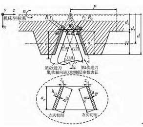
Due to the traditional radial layered cutting method, it is impossible to achieve the machining precision and surface quality of large pitch thread. In this paper, the axial layered cutting method is proposed for the machining characteristics of large pitch threads, as shown in Figure 1. In the picture,
n is the rotational speed of the workpiece,
vf is the tool axial feed velocity,
Vc is the main movement speed;
Κr1 is the main deflection angle of cutting tool for left edge cutting.
Κr2 right edge, the tool lead angle during cutting;
d is the outer diameter of the test piece,
D2 is the middle diameter of the test piece,
D1 is the small diameter of the test piece;
Ap is the total radial depth of cut,
Zlj is the left edge, a single machining allowance;
Zrk is the right edge, a single machining allowance;
hDl left edge of the tool, the cutting thickness when turning;
hDr the right edge of the tool, the cutting thickness when turning;
P is the thread pitch of the test part, R1 and R2 are the tooth radius of the left and right sides of the test piece, respectively; R1 and r2 are the radius of the left and right cusp of the tool, and α is the angle of the thread.
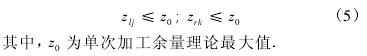
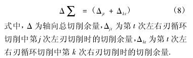
After, when finishing large pitch threads, only the left and right cutting edges are used to remove the process margin by alternating multiple feeds along the axis. Until the roughness of the machined surface of the left and right threads and the error of the thread diameter are controlled below the predetermined processing quality index. It can be seen from Fig. 1 that the axial layered cutting method is full-edge cutting. During each infeed, the depth of cut ap is constant and equal to the thread height H, and the area of the cutting layer is only related to the axial single machining allowance.
The relationship between the variables is as follows:
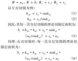
It can be known from the above formula. This embodiment uses a full cutting edge of the cutting, after which each feed, involved in cutting length of the cutting edge unchanged. The area of the cutting layer during cutting is related to the axial single machining allowance and the total radial depth of cut. Therefore, when large pitch threads are machined by axial layered cutting, the formation of thread surface is closely related to the state of the cutting edge of the tool.
Since the cutting force is closely related to the cutting layer parameters, and the cutting force should be less than the maximum bearing capacity of the workpiece material. Therefore, the area of the cutting layer should be less than a certain fixed value, that is, the cutting parameters should be controlled during the processing. Therefore, the following formula can be obtained:
Through the above-mentioned axial layered cutting method, the contact relationship of the cutter and the parameters of the cutting layer can be obtained, and the key control variables of the axially layered cutting mode of the large pitch thread are shown in Table 1.

In Table 1,
Zi is a single machining allowance for axial layering cutting;
γ0 is the rake angle of the cutting edge.
α01 is the left cutting edge back angle,
α02 is the right cutting edge back angle,
εr1 is the cutting edge angle of the left cutting edge.
εr2 is the right cutting edge angle;
j is the left edge, the number of times of continuous cutting,
k is the right edge, the number of times of continuous cutting,
T is the left and right edge, and the number of cutting cycles.
2, axial layering cutting process design method
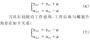
Axially graded steep thread cutting process, due to the presence of the thread helix angle, resulting in a change in the cutting plane. In the process of cutting, the working angle of the left and right edges changes, which is no longer equal to the actual marked angle, and the difference between the left and right edges increases, which will affect the consistency of the left and right surface of the thread. Therefore, the design of the tool must consider the influence of the helix angle on the working angle of the left and right blades, and make a reasonable structural design. The main influences in the cutting process are the rake angle and the back angle of the tool. The working front angle, working back angle and spiral angle of the left cutting edge of the tool have the following relationship:
In the formula,
γ0e1 is the working angle of the left cutting edge.
α0e1, which is the working back angle of the left cutting edge.
γ0e2, which is the working rake angle of the right cutting edge.
α0e2, the working cutting angle of the right cutting edge,
φ is the helix angle. Therefore, in order to make the screw left and right thread surface processing consistency, the process design, the rational design of the left and right cutting edge angle. The design should be followed, the left cutting edge rake angle is smaller than the right cutting edge, and the difference is roughly equal to twice the helix angle; The left cutting edge back angle is larger than the right cutting edge, and the difference is also roughly equal to twice the spiral angle.
At the same time, when the large-pitch thread finishing is performed by the axial layer cutting method, if the number of cuttings is too small, the thread surface that satisfies the processing quality cannot be obtained. If the number of cutting times is large, the tool life will be shortened due to the accumulation of cutting heat and cutting force during multiple cutting. Thereby affecting the threaded surface, so that the processing effect is reduced; Therefore, the values of j, k, and t should be reasonably designed to be minimized on the premise that the thread surface processing requirements are met. The relationship is:
Cutting efficiency is not only related to the cutting order, but also has a certain relationship with the three factors of cutting amount. Whether the design of cutting parameters is reasonable or not is very important to the production efficiency, processing cost and product quality of cutting. Using reasonable cutting parameters can significantly reduce processing costs and improve processing efficiency. Therefore, when designing the process plan, the appropriate cutting parameters should be selected. The order of selection should be: First try to choose the maximum radial depth of cut ap, Then select the appropriate machining allowance zi according to the processing conditions. And finally in the case where the tool life or the power allowed by the machine, select the appropriate cutting speed vc. From the above analysis, high efficiency and high surface consistency are critical to thread cutting during thread machining. Consistency is the key to ensuring the best quality and productivity of thread turning.
Therefore, the process design goal of the axially layered cutting method of large pitch thread is proposed, as shown in Table 2.
In Table 2, η is the processing efficiency, which is inextricably linked to tool life and processing order; ΔP is the pitch error of the thread surface, which is divided into the left thread surface pitch error and the right thread surface pitch error, both of which should be smaller than the screw technical requirement ΔP0; γij is used to reveal the consistency of the pitch error of the left and right thread faces, and the larger the value, the higher the consistency; Ra is the arithmetic mean deviation of the surface profile, which is used to reveal the surface roughness of the left and right thread faces. Both of which should be less than about the screw threaded surface of the technical requirements of surface roughness values Ra0.
From the above analysis, under the premise of meeting the technical requirements, the cutting efficiency, the consistency of the surface of the left and right thread surface is the design goal. Taking the tool geometry angle, cutting parameters and cutting times as design variables, the design method of axially layered cutting process for large pitch thread is proposed, as shown in Fig. 2.
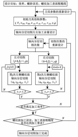
The design goal is to cut the machining efficiency and the surface consistency of the left and right thread surfaces. The tool geometry, cutting parameters and cutting order are used as design variables. The design method of axially layered cutting process for large pitch thread is proposed. Design and grind two tools, propose a matching process design, and carry out a comparison experiment of turning large pitch thread cutting technology.
The experimental results show that the process scheme obtained by this design method: The large pitch thread can be significantly improved in pitch error, machining surface morphology and distribution, and meet the requirements of large pitch thread processing quality.
Key word: Thread; Large screw pitch; Turning; Axial layered cutting; process planning
Introduction
The thread with a pitch greater than 4 mm is defined as a large pitch thread. It belongs to non-standard parts, and the tooth profile is wide and deep. These large pitch threads are commonly used for the screw and nut of large press adjustment assemblies, as well as the port threads on self-propelled guns, and play an important role in each equipment. Therefore, to study the cutting method of large pitch thread, it is proposed that the process design method of large pitch thread is essential to ensure and improve the adjustment and assembly precision. The existing researches mainly deal with the processing method and precision control method of small and medium pitch thread, and do not consider the case of large pitch thread with non-standard pitch. It is impossible to specifically disclose the processing and precision control method of large pitch thread. The existing research mainly focuses on the processing methods and precision control methods of medium and small pitch threads, without considering the situation of non-standard large pitch threads, and can not reveal the processing and precision control methods of large pitch threads concretely. Large pitch threads have a large removal margin, so it is impossible to finish threads in one cutting. The finishing stage of large pitch threads needs to be completed by multiple feeds. In the axial stratified cutting process of large pitch thread, if the number of cutting is too small, the thread surface that meets the processing quality requirements cannot be obtained. If the number of cutting times is large, the accumulation of cutting heat and cutting force during multiple cutting will shorten the tool life. , thereby affecting the surface quality of the thread processing, so that the processing effect is reduced; Therefore, when using the axial layering turning method for large pitch thread finishing, there must be a corresponding design method to ensure that the number of cutting times is used to obtain the highest thread surface quality. In this paper, under the premise of meeting the technical requirements, the cutting efficiency and the consistency of the surface of the left and right thread surface are designed. The tool geometry angle, cutting parameters and cutting times are used as design variables to reveal the constraint relationship between variables. The design method of axially layered cutting process for large pitch thread is proposed. According to the method, two different process schemes are designed, and the comparison experiment of large pitch thread finishing is carried out to verify the correctness of the design method.
1. Axial layered cutting method and its cutting layer parameters
Due to the traditional radial layered cutting method, it is impossible to achieve the machining precision and surface quality of large pitch thread. In this paper, the axial layered cutting method is proposed for the machining characteristics of large pitch threads, as shown in Figure 1. In the picture,
n is the rotational speed of the workpiece,
vf is the tool axial feed velocity,
Vc is the main movement speed;
Κr1 is the main deflection angle of cutting tool for left edge cutting.
Κr2 right edge, the tool lead angle during cutting;
d is the outer diameter of the test piece,
D2 is the middle diameter of the test piece,
D1 is the small diameter of the test piece;
Ap is the total radial depth of cut,
Zlj is the left edge, a single machining allowance;
Zrk is the right edge, a single machining allowance;
hDl left edge of the tool, the cutting thickness when turning;
hDr the right edge of the tool, the cutting thickness when turning;
P is the thread pitch of the test part, R1 and R2 are the tooth radius of the left and right sides of the test piece, respectively; R1 and r2 are the radius of the left and right cusp of the tool, and α is the angle of the thread.
figure 1 Axial stratified cutting method and tool contact relationship
Since the roughing and semi-finishing processes are finished, the radial dimensions and shape dimensions of the external threads meet the finishing requirements; Therefore, when the large pitch thread is finished, only the left and right cutting edges are used, and the machining allowance is removed by alternately cutting the layers in the axial direction;After, when finishing large pitch threads, only the left and right cutting edges are used to remove the process margin by alternating multiple feeds along the axis. Until the roughness of the machined surface of the left and right threads and the error of the thread diameter are controlled below the predetermined processing quality index. It can be seen from Fig. 1 that the axial layered cutting method is full-edge cutting. During each infeed, the depth of cut ap is constant and equal to the thread height H, and the area of the cutting layer is only related to the axial single machining allowance.
The relationship between the variables is as follows:
It can be known from the above formula. This embodiment uses a full cutting edge of the cutting, after which each feed, involved in cutting length of the cutting edge unchanged. The area of the cutting layer during cutting is related to the axial single machining allowance and the total radial depth of cut. Therefore, when large pitch threads are machined by axial layered cutting, the formation of thread surface is closely related to the state of the cutting edge of the tool.
Since the cutting force is closely related to the cutting layer parameters, and the cutting force should be less than the maximum bearing capacity of the workpiece material. Therefore, the area of the cutting layer should be less than a certain fixed value, that is, the cutting parameters should be controlled during the processing. Therefore, the following formula can be obtained:
Through the above-mentioned axial layered cutting method, the contact relationship of the cutter and the parameters of the cutting layer can be obtained, and the key control variables of the axially layered cutting mode of the large pitch thread are shown in Table 1.
In Table 1,
Zi is a single machining allowance for axial layering cutting;
γ0 is the rake angle of the cutting edge.
α01 is the left cutting edge back angle,
α02 is the right cutting edge back angle,
εr1 is the cutting edge angle of the left cutting edge.
εr2 is the right cutting edge angle;
j is the left edge, the number of times of continuous cutting,
k is the right edge, the number of times of continuous cutting,
T is the left and right edge, and the number of cutting cycles.
2, axial layering cutting process design method
Axially graded steep thread cutting process, due to the presence of the thread helix angle, resulting in a change in the cutting plane. In the process of cutting, the working angle of the left and right edges changes, which is no longer equal to the actual marked angle, and the difference between the left and right edges increases, which will affect the consistency of the left and right surface of the thread. Therefore, the design of the tool must consider the influence of the helix angle on the working angle of the left and right blades, and make a reasonable structural design. The main influences in the cutting process are the rake angle and the back angle of the tool. The working front angle, working back angle and spiral angle of the left cutting edge of the tool have the following relationship:
In the formula,
γ0e1 is the working angle of the left cutting edge.
α0e1, which is the working back angle of the left cutting edge.
γ0e2, which is the working rake angle of the right cutting edge.
α0e2, the working cutting angle of the right cutting edge,
φ is the helix angle. Therefore, in order to make the screw left and right thread surface processing consistency, the process design, the rational design of the left and right cutting edge angle. The design should be followed, the left cutting edge rake angle is smaller than the right cutting edge, and the difference is roughly equal to twice the helix angle; The left cutting edge back angle is larger than the right cutting edge, and the difference is also roughly equal to twice the spiral angle.
At the same time, when the large-pitch thread finishing is performed by the axial layer cutting method, if the number of cuttings is too small, the thread surface that satisfies the processing quality cannot be obtained. If the number of cutting times is large, the tool life will be shortened due to the accumulation of cutting heat and cutting force during multiple cutting. Thereby affecting the threaded surface, so that the processing effect is reduced; Therefore, the values of j, k, and t should be reasonably designed to be minimized on the premise that the thread surface processing requirements are met. The relationship is:
Cutting efficiency is not only related to the cutting order, but also has a certain relationship with the three factors of cutting amount. Whether the design of cutting parameters is reasonable or not is very important to the production efficiency, processing cost and product quality of cutting. Using reasonable cutting parameters can significantly reduce processing costs and improve processing efficiency. Therefore, when designing the process plan, the appropriate cutting parameters should be selected. The order of selection should be: First try to choose the maximum radial depth of cut ap, Then select the appropriate machining allowance zi according to the processing conditions. And finally in the case where the tool life or the power allowed by the machine, select the appropriate cutting speed vc. From the above analysis, high efficiency and high surface consistency are critical to thread cutting during thread machining. Consistency is the key to ensuring the best quality and productivity of thread turning.
Therefore, the process design goal of the axially layered cutting method of large pitch thread is proposed, as shown in Table 2.
Table 2 Axial delamination cutting process design goals
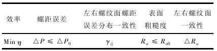
In Table 2, η is the processing efficiency, which is inextricably linked to tool life and processing order; ΔP is the pitch error of the thread surface, which is divided into the left thread surface pitch error and the right thread surface pitch error, both of which should be smaller than the screw technical requirement ΔP0; γij is used to reveal the consistency of the pitch error of the left and right thread faces, and the larger the value, the higher the consistency; Ra is the arithmetic mean deviation of the surface profile, which is used to reveal the surface roughness of the left and right thread faces. Both of which should be less than about the screw threaded surface of the technical requirements of surface roughness values Ra0.
From the above analysis, under the premise of meeting the technical requirements, the cutting efficiency, the consistency of the surface of the left and right thread surface is the design goal. Taking the tool geometry angle, cutting parameters and cutting times as design variables, the design method of axially layered cutting process for large pitch thread is proposed, as shown in Fig. 2.
Figure 2 Axial layered cutting design flow


