Processing Technology of Metal Disc Parts
In CNC machining, whether manual or automatic programming, process analysis of the machined parts before programming, formulate the process plan, select the appropriate tool, and determine the amount of cutting. In programming, some process problems (such as tool setting point, processing route, etc.) also need to be dealt with. Therefore, the process of NC programming is a very important task. The main purpose of this paper is to discuss the process of metal disc parts processing. It mainly includes blank selection, reference selection, processing sequence, clamping method, surface processing, parameter selection, and process route.
1. The general process of CNC machining process design
(1) Select the CNC machine tool suitable for machining the part and determine the process content.
(2) Analyze the drawings of machined parts, clarify the processing content and technical requirements, determine the processing plan, and develop the CNC machining route. Such as the division of the process, the arrangement of the processing sequence, the connection of non-CNC machining processes, and so on. Design CNC machining processes, such as the division of processes, the selection of tools, the positioning and installation of fixtures, the determination of the amount of cutting, the determination of the route of the cutter, and so on. Due to the variety of parts and the contours and shapes of the parts, the material and size of the blanks are not the same.
Therefore, the process design in CNC machining determines the use efficiency of CNC machine tools, the processing quality of parts, the number of tools and economics. We should try to ensure centralized processing step, the shortest route and machine the auxiliary process time is minimized.
2. Analysis of processing technology of disc parts
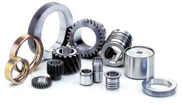
(1) Selection of processing materials. Disk parts mainly of steel, cast iron, stainless steel, aluminum, brass, bronze or the like as the main raw material. Hot-rolled or cold-drawn rods are usually used for small diameter discs. Different materials may choose solid casting. A pre-hole can be used when the aperture is large. If mass-produced, the optional cold extrusion and other advanced blank manufacturing process, not only can improve productivity can also save material.
(2) Selection of processing standards.
According to the characteristics of the parts, the principle of standard overlap and benchmarking should be met as much as possible. The basis for selection is usually the end face, the inner hole and the outer circle. When the end face is used as the datum for disc parts, the plane is generally used as the datum. When the disc parts are based on the inner hole, the end face is generally assisted by the end face; The outer circle reference method is basically the same as the reference selection with the inner hole.
(3) Process arrangement
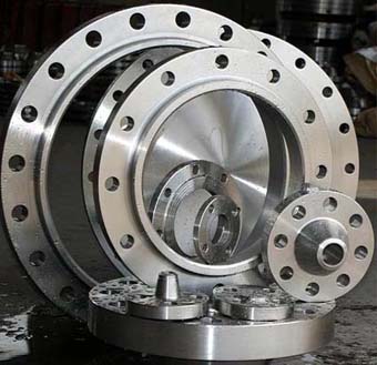
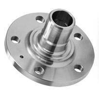
Typical disc parts typically consist of end faces, holes and outer faces (some also include stepped holes), and disc parts are characterized by a radial dimension greater than the axial dimension. Please look for the disk-type parts factory Kang Ding, quality assurance. For disc parts, there are not only dimensional requirements but also surface roughness requirements, which usually include requirements for radial runout, round runout and verticality. The round runout and the end face round run are the key considerations when formulating the machining process of the disk parts. After finishing, the outer circle, hole and end face should be finished in one clamping process to avoid second clamping. For the parts that need to be clamped multiple times, the holes are machined first, and then the outer circle or end face is machined through the holes.
(4) Selection and use of fixtures.
The universal three-jaw chuck is used to clamp the workpieces of small disc parts. The four-jaw chuck or face plate is suitable for the clamping of medium and large disc parts. For the accuracy of the tangential position, it is usually processed by clamping with a mandrel or a faceplate. When the positioning standard of the disc parts is the machined hole, in order to ensure the coaxiality of the outer circle axis and the hole axis, the mandrel method is used to clamp the parts. There are also many types of mandrels. Cylindrical mandrel or small taper mandrel, suitable for positioning with cylindrical holes; And those special holes such as taper holes and thread holes adopt corresponding cones and thread mandrels. Cylindrical mandrel clamps parts by centring the outer cylindrical surface and pressing the end surface. A clearance fit is used between the mandrel and the part hole.
In order to improve the positioning accuracy of the spindle, sometimes the spindle is processed into a small taper vertebral body. There is also a common fixture disc for large disc sleeve parts. The disc is mounted on the large disc of the lathe spindle. It is generally suitable for irregular shape workpieces, and can not be used when the general chuck clamping. When using the disc to clamp the workpiece, it must be balanced, otherwise centrifugal force will be generated, which will eventually cause vibration and lead to wear and tear of the spindle bearing.
(5) Processing of finished surface of disc parts
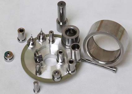
For the rotary surface of the disc parts, roughing is performed by turning. For finishing, more consideration should be given to material, processing requirements and output to select processing methods, such as finishing turning, finishing finishing, finishing grinding and so on. For the non-rotating surface of the disc parts, the corresponding processing methods, milling, EDM, etc. can be used.
(6) Determination of cutting parameters.
When the programmer chooses the cutting amount, he must fully consider various factors affecting the cutting, correctly select the cutting conditions, and reasonably determine the cutting amount, which can effectively improve the machining quality and efficiency. Factors affecting cutting conditions are:
① machine, tool and workpiece rigidity;
② cutting speed, depth of cut, cutting feed rate;
③ accuracy and surface roughness of the workpiece;
④ maximum tool life expectancy and productivity;
⑤ types of cutting fluid, cooling method;
⑥ hardness of the workpiece material heat treatment;
⑦ number of workpieces;
⑧ life of the machine.
Among the above factors, the feed rate, cutting speed and depth of cut are the main factors. Mainly analyze these points:
A, the choice of feed rate
Each revolution of the workpiece, the distance the tool moves in the direction of travel is called the feed amount, and the unit is mm/r. In theory, when roughing, it is the maximum feed of the mechanism. The feed rate is limited by the size of some of the following factors: Strength and stiffness of machine tools, shanks, blades, fixtures. The finishing is mainly limited by the machining accuracy and surface roughness, and the feed amount is selected in combination with the workpiece material, the radius of the tool nose and the cutting speed.
B, the choice of cutting speed
The linear velocity of the main motion is called the cutting speed and its unit is III/s or III/min. In actual production, the cutting speed is usually selected based on experience, and the lower cutting speed is generally selected for roughing. For fine turning, choose a higher cutting speed. In addition, it is necessary to comprehensively consider the processing properties of the material, the cutting performance of the tool, the working conditions and other factors to reasonably determine the optimal cutting speed. The cutting speed is related to the machine speed, and there is a calculation conversion formula:
n=1000v/dII
Formula where: d is the diameter of the workpiece, the selected speed n should be within the range of the rotational speed of the lathe. The appropriate processing parameters are selected by experience or the above calculation formula.
(7) Formulate processing routes.
The biggest difference between disc parts and shaft parts is the way they are installed during machining. Sometimes the various feature requirements of the part also result in a completely different machining method than the shaft part. Typical disc parts We usually use the following processing techniques: Preparation of blank-blank removal stress treatment A roughing surface of a roughing surface semi-finishing and finishing a non-rotating plane processing a deburring treatment a heat treatment (quenching, tempering, etc.) a finished surface inspection.
Kang Ding processing companies are: Rotary top, screw, machine tool spindle, shaft machining, high precision tool holder, tool holder, elastic chuck, non-standard parts processing, machine tool post is the company's flagship product!
1. The general process of CNC machining process design
(1) Select the CNC machine tool suitable for machining the part and determine the process content.
(2) Analyze the drawings of machined parts, clarify the processing content and technical requirements, determine the processing plan, and develop the CNC machining route. Such as the division of the process, the arrangement of the processing sequence, the connection of non-CNC machining processes, and so on. Design CNC machining processes, such as the division of processes, the selection of tools, the positioning and installation of fixtures, the determination of the amount of cutting, the determination of the route of the cutter, and so on. Due to the variety of parts and the contours and shapes of the parts, the material and size of the blanks are not the same.
Therefore, the process design in CNC machining determines the use efficiency of CNC machine tools, the processing quality of parts, the number of tools and economics. We should try to ensure centralized processing step, the shortest route and machine the auxiliary process time is minimized.
2. Analysis of processing technology of disc parts
(1) Selection of processing materials. Disk parts mainly of steel, cast iron, stainless steel, aluminum, brass, bronze or the like as the main raw material. Hot-rolled or cold-drawn rods are usually used for small diameter discs. Different materials may choose solid casting. A pre-hole can be used when the aperture is large. If mass-produced, the optional cold extrusion and other advanced blank manufacturing process, not only can improve productivity can also save material.
(2) Selection of processing standards.
According to the characteristics of the parts, the principle of standard overlap and benchmarking should be met as much as possible. The basis for selection is usually the end face, the inner hole and the outer circle. When the end face is used as the datum for disc parts, the plane is generally used as the datum. When the disc parts are based on the inner hole, the end face is generally assisted by the end face; The outer circle reference method is basically the same as the reference selection with the inner hole.
(3) Process arrangement
Typical disc parts typically consist of end faces, holes and outer faces (some also include stepped holes), and disc parts are characterized by a radial dimension greater than the axial dimension. Please look for the disk-type parts factory Kang Ding, quality assurance. For disc parts, there are not only dimensional requirements but also surface roughness requirements, which usually include requirements for radial runout, round runout and verticality. The round runout and the end face round run are the key considerations when formulating the machining process of the disk parts. After finishing, the outer circle, hole and end face should be finished in one clamping process to avoid second clamping. For the parts that need to be clamped multiple times, the holes are machined first, and then the outer circle or end face is machined through the holes.
(4) Selection and use of fixtures.
The universal three-jaw chuck is used to clamp the workpieces of small disc parts. The four-jaw chuck or face plate is suitable for the clamping of medium and large disc parts. For the accuracy of the tangential position, it is usually processed by clamping with a mandrel or a faceplate. When the positioning standard of the disc parts is the machined hole, in order to ensure the coaxiality of the outer circle axis and the hole axis, the mandrel method is used to clamp the parts. There are also many types of mandrels. Cylindrical mandrel or small taper mandrel, suitable for positioning with cylindrical holes; And those special holes such as taper holes and thread holes adopt corresponding cones and thread mandrels. Cylindrical mandrel clamps parts by centring the outer cylindrical surface and pressing the end surface. A clearance fit is used between the mandrel and the part hole.
In order to improve the positioning accuracy of the spindle, sometimes the spindle is processed into a small taper vertebral body. There is also a common fixture disc for large disc sleeve parts. The disc is mounted on the large disc of the lathe spindle. It is generally suitable for irregular shape workpieces, and can not be used when the general chuck clamping. When using the disc to clamp the workpiece, it must be balanced, otherwise centrifugal force will be generated, which will eventually cause vibration and lead to wear and tear of the spindle bearing.
(5) Processing of finished surface of disc parts
For the rotary surface of the disc parts, roughing is performed by turning. For finishing, more consideration should be given to material, processing requirements and output to select processing methods, such as finishing turning, finishing finishing, finishing grinding and so on. For the non-rotating surface of the disc parts, the corresponding processing methods, milling, EDM, etc. can be used.
(6) Determination of cutting parameters.
When the programmer chooses the cutting amount, he must fully consider various factors affecting the cutting, correctly select the cutting conditions, and reasonably determine the cutting amount, which can effectively improve the machining quality and efficiency. Factors affecting cutting conditions are:
① machine, tool and workpiece rigidity;
② cutting speed, depth of cut, cutting feed rate;
③ accuracy and surface roughness of the workpiece;
④ maximum tool life expectancy and productivity;
⑤ types of cutting fluid, cooling method;
⑥ hardness of the workpiece material heat treatment;
⑦ number of workpieces;
⑧ life of the machine.
Among the above factors, the feed rate, cutting speed and depth of cut are the main factors. Mainly analyze these points:
A, the choice of feed rate
Each revolution of the workpiece, the distance the tool moves in the direction of travel is called the feed amount, and the unit is mm/r. In theory, when roughing, it is the maximum feed of the mechanism. The feed rate is limited by the size of some of the following factors: Strength and stiffness of machine tools, shanks, blades, fixtures. The finishing is mainly limited by the machining accuracy and surface roughness, and the feed amount is selected in combination with the workpiece material, the radius of the tool nose and the cutting speed.
B, the choice of cutting speed
The linear velocity of the main motion is called the cutting speed and its unit is III/s or III/min. In actual production, the cutting speed is usually selected based on experience, and the lower cutting speed is generally selected for roughing. For fine turning, choose a higher cutting speed. In addition, it is necessary to comprehensively consider the processing properties of the material, the cutting performance of the tool, the working conditions and other factors to reasonably determine the optimal cutting speed. The cutting speed is related to the machine speed, and there is a calculation conversion formula:
n=1000v/dII
Formula where: d is the diameter of the workpiece, the selected speed n should be within the range of the rotational speed of the lathe. The appropriate processing parameters are selected by experience or the above calculation formula.
(7) Formulate processing routes.
The biggest difference between disc parts and shaft parts is the way they are installed during machining. Sometimes the various feature requirements of the part also result in a completely different machining method than the shaft part. Typical disc parts We usually use the following processing techniques: Preparation of blank-blank removal stress treatment A roughing surface of a roughing surface semi-finishing and finishing a non-rotating plane processing a deburring treatment a heat treatment (quenching, tempering, etc.) a finished surface inspection.
Kang Ding processing companies are: Rotary top, screw, machine tool spindle, shaft machining, high precision tool holder, tool holder, elastic chuck, non-standard parts processing, machine tool post is the company's flagship product!


