Understanding the Structural Design Criteria of 10 NC Cutting Metal Parts
Guide: The criteria for easy tool withdrawal in part processing and design are as follows: After finishing the processing task of a processing surface, the cutting tool can leave the area conveniently, so as to avoid collision or damage of the machined surface between the cutting tool and the workpiece, and ensure the smooth processing of the whole process. Convenient tool withdrawal can save processing time, thus achieving the goal of reducing processing costs.
Design Criteria for Parts Cutting Parts Structure:
Cutting is the most common processing method in machinery industry, which includes turning, milling, boring, planer, grinding, drilling, etc.
The structural design of cutting parts should fully consider the characteristics of processing technology.
1) Guidelines for advancing and withdrawing knives:
1) Guidelines for advancing and withdrawing knives:
The criterion of easy tool withdrawal is to enable the cutting tool to leave the machined surface conveniently after finishing the processing task, so as to avoid collision or damage of the machined surface between the tool and the workpiece. Ensure that the processing goes smoothly.
Convenient tool withdrawal can save processing time, thus achieving the goal of reducing processing costs.
Engineering application examples:
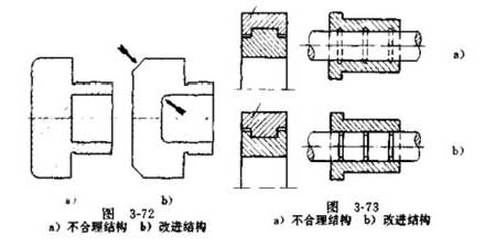
(1) When the outer circle, the inner circle and the plane are ground, the transition point between the surfaces should be designed to make the over-travel groove to ensure the free exit of the grinding wheel and leave the processing space. (In grinding process, if there is no possibility of tool withdrawal at the end of the grinding wheel travel, the grinding time is long and the heat is much higher at the end of the travel. This may result in secondary quenching and grinding cracks, and the knife withdrawal groove is the most common structural design measure to facilitate the knife withdrawal. )
(2) When grinding the stepped shaft, the grinding wheel overpass groove should be set at the stepped part of the shaft.
(3) When designing the cone surface structure, it is necessary to consider the convenience of retracting the knife.
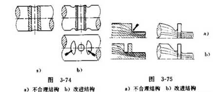
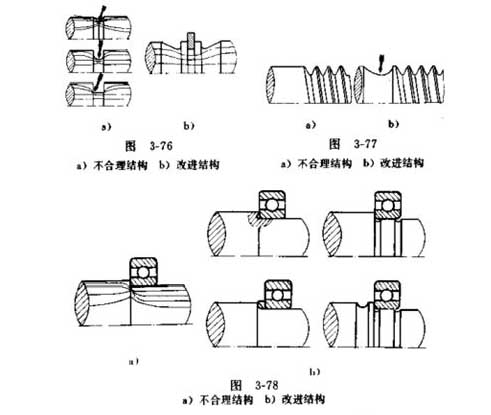
(4) When processing external threads, the tool withdrawal groove should be set aside. When processing the inner thread of blind hole, there should be enough retracting groove at the end of the thread.
(5) Milling and planer processing should also ensure the possibility of tool withdrawal, otherwise, the whole process of processing can not be guaranteed smoothly.
For example, when drilling, there should be a large amount of drilling space to ensure fast drilling.
2) Guidelines for reducing processing volume:
Reducing the amount of processing means reducing processing time and saving on raw materials, which reduces component manufacturing costs.
Common methods to reduce the amount of cutting:
(1) Select a suitable blank so that the shape of the blank is as close as possible to the shape of the member. When designing a cutting member that requires a large inner and outer diameter, the structure should be designed to directly adopt the pipe material under the premise of ensuring its functional requirements;
(2) Composite components are used. When the cutting amount of the member is excessively large, the overall structure can be changed to a combined structure composed of a plurality of single pieces.
(3) Slow transition, unless functional requirements, should avoid sudden cross-sectional mutations.
(4) Reduce the itinerary. The groove needs to be milled. To reduce the stroke of the milling cutter, the number of grooves should be designed to be odd.
3) Reduce the number of machined surfaces and the area of machined surfaces.
(1) Turning the end face instead of the countersink end face.
(2) The diameter of the middle part of the inner circular hole is increased to reduce the surface length of the finishing car;
(3) making the bottom surface of the bearing seat a step support surface to reduce the processing surface;
(4) Change the processing plane of the base with a larger area to the hollow surface to reduce the grinding surface;
(5) If only a small section of the outer surface of the shaft with shorter length and higher precision is required, the stepped shaft should be used.
4) Reliable clamping guidelines: Avoid clamping surfaces that are too small.
Engineering application examples:
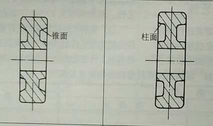
(1) making a partial cylindrical clamping process surface in the tapered portion of the part;
(2) Improve the structure of the parts and increase the contact surface between the claws and the parts to be processed, so that the clamping is reliable;
(3) In order to facilitate the processing of the rail surface of the column, a process boss is made on the curved surface to facilitate the clamping. Milling the process boss after finishing the machining;
(4) Try to make multiple faces of the structure to be processed in the same plane.
5) The same clamping process guidelines:
If the two cutting faces on the same component are not machined in the same clamping process, the position tolerance accuracy between them is difficult to improve. In addition, multiple disassembly and assembly also lengthens the processing time and increases the manufacturing cost. Therefore, the components should be processed under the same clamping conditions as much as possible, which is a one-time forming criterion.
In order to ensure one-time forming, the dimension of cutting parts should be changed unidirectionally. Moreover, the shaft diameter should be made larger as much as possible, and the aperture diameter becomes smaller in turn, which is more advantageous in mass production.
Engineering application examples:
(1) Add a thimble hole or add another clamping surface to ensure that the two machined surfaces can be processed under the same clamping conditions.
(2) The middle boss of the two bearing housing holes can be removed from the intermediate boss if conditions permit, and the retaining ring can be used instead to ensure that the two bearing holes can be processed at one time.
(4) When the outer circle of the part has coaxiality with the inner hole, the structure of the part should be changed into that the outer circle and the inner hole can be processed simultaneously after one clamping. (Additional clamping convex platform)
6) Convenient cutting guidelines:
Common measures for convenient cutting:
(1) Use a simple shape. In general, spherical and tapered structures should be avoided as much as possible, and cylindrical structures are preferred.
(2) Different inside and outside. The circular arc shape on the outer surface is difficult to process and should be chamfered (chamfered instead of rounded). The inner corner is designed to be circular and easy to machine.
(3) It should be avoided to machine the key groove or high-precision fit inside the structure (to avoid the concave surface and inner surface processing). Try to avoid setting the working surface in the low recess; The outer surface of box parts is easier to process than the inner surface. The fitting surface of the parts should be the outer surface as far as possible. It is easier to process the outer surface than the inner surface. It is more convenient to process the groove of the valve stem than to process the sinking groove of the hairpin sleeve, and the accuracy is easily guaranteed.
7) Reduce the gap effect criteria:
Because of the requirement of structure and function, many turning axles are designed with convex platform, shoulder, annular groove, radial perforation and other structures. These structures are usually caused by the notch effect, the origin of fatigue cracks, and an important cause of axial fatigue damage. Therefore, efforts should be made to avoid at least reducing the effects of such gaps.
There are three general combinations of methods:
(1) The transition between different sections is smooth.
(2) reduce the stiffness around the gap;
(3) Avoid sharp edges.
8) Avoid bevel opening criteria:
On the inclined surface, the hole is difficult to locate on the sharp corner. If the tool outlet hole end is beveled, the hole may be bent due to uneven surrounding constraints.
9) Through hole priority criteria:
The through hole is usually easier to process than the blind hole, and the processing quality is easily improved.
10) Similar criteria for the surrounding conditions of the hole:
The constraints around the hole are determined by the elasticity of the material, the shape of the member, and the condition of the support. If the hole is drilled in a place where the surrounding constraints are very different, the drill bit will be retracted to the side where the machining resistance is small, thereby drilling the bent hole.
Project example:
(1) When drilling glasses holes.
The machined holes should be filled with inserts of the same material, so that the whole circumference constraints are re-same, and then the second hole is processed.
11) The number of times the workpiece should be clamped should be minimized:
12) Standard tools should be used as much as possible to reduce the type of tools:
(1) The form and width of the undercut groove or keyway on the shaft should be as consistent as possible to reduce the type of tool;
(2) The size and specifications of each screw hole on the box should be as consistent as possible;
(3) Avoid using the structure of non-standard tools such as lengthened drills as far as possible.
(4) The fillet radius of the workpiece shall be in accordance with the specification and size of the standard cutter (milling cutter).
Design Criteria for Parts Cutting Parts Structure:
Cutting is the most common processing method in machinery industry, which includes turning, milling, boring, planer, grinding, drilling, etc.
The structural design of cutting parts should fully consider the characteristics of processing technology.
1) Guidelines for advancing and withdrawing knives:
1) Guidelines for advancing and withdrawing knives:
The criterion of easy tool withdrawal is to enable the cutting tool to leave the machined surface conveniently after finishing the processing task, so as to avoid collision or damage of the machined surface between the tool and the workpiece. Ensure that the processing goes smoothly.
Convenient tool withdrawal can save processing time, thus achieving the goal of reducing processing costs.
Engineering application examples:
(1) When the outer circle, the inner circle and the plane are ground, the transition point between the surfaces should be designed to make the over-travel groove to ensure the free exit of the grinding wheel and leave the processing space. (In grinding process, if there is no possibility of tool withdrawal at the end of the grinding wheel travel, the grinding time is long and the heat is much higher at the end of the travel. This may result in secondary quenching and grinding cracks, and the knife withdrawal groove is the most common structural design measure to facilitate the knife withdrawal. )
(2) When grinding the stepped shaft, the grinding wheel overpass groove should be set at the stepped part of the shaft.
(3) When designing the cone surface structure, it is necessary to consider the convenience of retracting the knife.
(4) When processing external threads, the tool withdrawal groove should be set aside. When processing the inner thread of blind hole, there should be enough retracting groove at the end of the thread.
(5) Milling and planer processing should also ensure the possibility of tool withdrawal, otherwise, the whole process of processing can not be guaranteed smoothly.
For example, when drilling, there should be a large amount of drilling space to ensure fast drilling.
2) Guidelines for reducing processing volume:
Reducing the amount of processing means reducing processing time and saving on raw materials, which reduces component manufacturing costs.
Common methods to reduce the amount of cutting:
(1) Select a suitable blank so that the shape of the blank is as close as possible to the shape of the member. When designing a cutting member that requires a large inner and outer diameter, the structure should be designed to directly adopt the pipe material under the premise of ensuring its functional requirements;
(2) Composite components are used. When the cutting amount of the member is excessively large, the overall structure can be changed to a combined structure composed of a plurality of single pieces.
(3) Slow transition, unless functional requirements, should avoid sudden cross-sectional mutations.
(4) Reduce the itinerary. The groove needs to be milled. To reduce the stroke of the milling cutter, the number of grooves should be designed to be odd.
3) Reduce the number of machined surfaces and the area of machined surfaces.
(1) Turning the end face instead of the countersink end face.
(2) The diameter of the middle part of the inner circular hole is increased to reduce the surface length of the finishing car;
(3) making the bottom surface of the bearing seat a step support surface to reduce the processing surface;
(4) Change the processing plane of the base with a larger area to the hollow surface to reduce the grinding surface;
(5) If only a small section of the outer surface of the shaft with shorter length and higher precision is required, the stepped shaft should be used.
4) Reliable clamping guidelines: Avoid clamping surfaces that are too small.
Engineering application examples:
(1) making a partial cylindrical clamping process surface in the tapered portion of the part;
(2) Improve the structure of the parts and increase the contact surface between the claws and the parts to be processed, so that the clamping is reliable;
(3) In order to facilitate the processing of the rail surface of the column, a process boss is made on the curved surface to facilitate the clamping. Milling the process boss after finishing the machining;
(4) Try to make multiple faces of the structure to be processed in the same plane.
5) The same clamping process guidelines:
If the two cutting faces on the same component are not machined in the same clamping process, the position tolerance accuracy between them is difficult to improve. In addition, multiple disassembly and assembly also lengthens the processing time and increases the manufacturing cost. Therefore, the components should be processed under the same clamping conditions as much as possible, which is a one-time forming criterion.
In order to ensure one-time forming, the dimension of cutting parts should be changed unidirectionally. Moreover, the shaft diameter should be made larger as much as possible, and the aperture diameter becomes smaller in turn, which is more advantageous in mass production.
Engineering application examples:
(1) Add a thimble hole or add another clamping surface to ensure that the two machined surfaces can be processed under the same clamping conditions.
(2) The middle boss of the two bearing housing holes can be removed from the intermediate boss if conditions permit, and the retaining ring can be used instead to ensure that the two bearing holes can be processed at one time.
(4) When the outer circle of the part has coaxiality with the inner hole, the structure of the part should be changed into that the outer circle and the inner hole can be processed simultaneously after one clamping. (Additional clamping convex platform)
6) Convenient cutting guidelines:
Common measures for convenient cutting:
(1) Use a simple shape. In general, spherical and tapered structures should be avoided as much as possible, and cylindrical structures are preferred.
(2) Different inside and outside. The circular arc shape on the outer surface is difficult to process and should be chamfered (chamfered instead of rounded). The inner corner is designed to be circular and easy to machine.
(3) It should be avoided to machine the key groove or high-precision fit inside the structure (to avoid the concave surface and inner surface processing). Try to avoid setting the working surface in the low recess; The outer surface of box parts is easier to process than the inner surface. The fitting surface of the parts should be the outer surface as far as possible. It is easier to process the outer surface than the inner surface. It is more convenient to process the groove of the valve stem than to process the sinking groove of the hairpin sleeve, and the accuracy is easily guaranteed.
7) Reduce the gap effect criteria:
Because of the requirement of structure and function, many turning axles are designed with convex platform, shoulder, annular groove, radial perforation and other structures. These structures are usually caused by the notch effect, the origin of fatigue cracks, and an important cause of axial fatigue damage. Therefore, efforts should be made to avoid at least reducing the effects of such gaps.
There are three general combinations of methods:
(1) The transition between different sections is smooth.
(2) reduce the stiffness around the gap;
(3) Avoid sharp edges.
8) Avoid bevel opening criteria:
On the inclined surface, the hole is difficult to locate on the sharp corner. If the tool outlet hole end is beveled, the hole may be bent due to uneven surrounding constraints.
9) Through hole priority criteria:
The through hole is usually easier to process than the blind hole, and the processing quality is easily improved.
10) Similar criteria for the surrounding conditions of the hole:
The constraints around the hole are determined by the elasticity of the material, the shape of the member, and the condition of the support. If the hole is drilled in a place where the surrounding constraints are very different, the drill bit will be retracted to the side where the machining resistance is small, thereby drilling the bent hole.
Project example:
(1) When drilling glasses holes.
The machined holes should be filled with inserts of the same material, so that the whole circumference constraints are re-same, and then the second hole is processed.
11) The number of times the workpiece should be clamped should be minimized:
12) Standard tools should be used as much as possible to reduce the type of tools:
(1) The form and width of the undercut groove or keyway on the shaft should be as consistent as possible to reduce the type of tool;
(2) The size and specifications of each screw hole on the box should be as consistent as possible;
(3) Avoid using the structure of non-standard tools such as lengthened drills as far as possible.
(4) The fillet radius of the workpiece shall be in accordance with the specification and size of the standard cutter (milling cutter).


