Sheet Metal Processing Chassis, Cabinet Inspection Standard
This standard is applicable to the inspection and acceptance of sheet metal processing cabinets and cabinet structural parts. It is a summary and supplement to the basic and routine technical requirements that are not exhaustively listed on the design documents or that are not necessarily specified.
This standard shall be accompanied by a reference to the technical requirements identified on the design document. The provisions other than the accuracy specified by the standard shall be proposed by the designer, the quality inspection department shall be implemented, or may be implemented in accordance with this standard on the basis of the consent of the designer.
The inspection and acceptance site may be at the place of arrival of the product designated by the contractor or Party A, and the results shall be consistent, and the final result shall be the final result.
2. Reference Standard Enterprise Standard Q/DMBM307-1997: Inspection sampling rules.
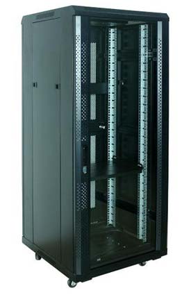
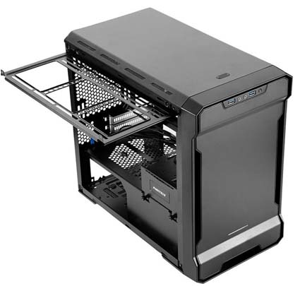
3. Cabinet
3.1 Dimensional Tolerance
3.2 Geometric tolerance
Sheet metal cabinet does not allow visible or partial tilting or twisting phenomenon.
The vertical dimension of the frame column and the base is less than 1.5 mm. When testing, the upper surface of the base is used as the reference, and the inner surface of the upper end of the column is used as the measuring point.
The parallelism between the top frame and the base is less than 1 mm. The detection points are the upper surface of the base and the lower surface of the top frame, and are mutually referenced. It can also be detected by measuring the length of the diagonal of six sides, and the difference should not exceed 2.5 mm. In the case of a middle partition, the parallelism of the top frame and the base can be relaxed to 1.5 mm, and the parallelism of the middle partition to the top frame or the base is less than 1 mm.
The absolute value of the difference between the diagonal lines of the upper and lower frames is less than 1.5 mm.
Upright column can't be distorted. The degree of parallelism between the two ends of each upright column connected with the upper and lower enclosure and the adjacent plane of the enclosure is less than 0.5mm.
3.3 Slide way supporting carriage.
The parallelism of the working face composed of the left and right slideways on the same floor relative to the upper surface of the base is 1 mm, and the absolute value of the gap between the adjacent two panels after the cartridge is loaded shall not exceed 0.6 mm.
3.4 The front, rear and left and right doors are not allowed to bulge or twist, and the flatness is less than 2 mm. Local 100mmX100mm shall not exceed 0.4mm. After all the door panels are installed in the cabinet, the outer surface of the door panel shall not exceed 1.5 mm parallel to the side of the cabinet where it is located. The absolute value of the difference between the parallel slots is less than 2 mm, and the frame is well fitted. The absolute value of the difference between the fixed gaps of the fixed door panel is ≤1mm; The rotating door panel can not have obvious drooping or upturning, and the absolute value of the difference between the same gap is ≤1.8mm. Doors with opening and closing requirements must be flexible to rotate. The opening angle is ≥90°. After closing, the magnetic adsorption is good with the door. There must be no interference during the rotation process that can cause damage to the sprayed layer. Side door assembly and disassembly should be flexible. The rotating door panel is placed at a position of about 30°, and the vertical distance from one side of the rotating shaft to the front plane of the frame is measured. The difference between the maximum value and the minimum value should be ≤10 mm.
4. The enclosure and the insertion frame
4.1 The flatness of the bottom and other sides of the cabinet is 1mm.
4.2 The verticality of the front and rear of the cabinet or the left and right facades relative to the bottom surface is 1mm.
4.3 The top and bottom surfaces of the panel have a parallelism of 0.5 mm and the side and bottom surfaces have a vertical dimension of 0.5 mm.
4.4 After the panel is installed in the box, it should be vertical and straight, the side of which is perpendicular to the bottom of the box is 0.5mm, and the parallelism between the bottom and the bottom of the box is 0.5mm.
4.5 To install the circuit board or the chassis frame, you need to use the tooling analog circuit board or chassis for assembly. When loading and unloading the tool box, it should be smooth. After loading the box, it should be properly and stable, without floating or loosening. The hard-wired connector should be accurate and insert and pull out without abnormal block.
5. Parts
5.1 The material should meet the requirements of the drawings.
Unless otherwise specified, all steel sheets are made of high-quality 20# cold-rolled steel sheets. Hot-rolled steel sheets are not allowed. Material substitution must be approved by technicians.
5.2 The tolerance of bending angle is not more than ±1°
5.3 For parts without shape and position tolerance, the straightness and flatness are inspected according to the C-level accuracy specified in GB1184-80 (including all contour lines and planes).
5.4 Deformation caused during processing, should be adjusted straight after forming.
5.5 Parts are processed correctly according to the drawings. All edges and edges should be blunt, and the height of burrs and flash edges should not exceed 0.2 mm. In principle, no hand is used as a guideline.
5.6 The pressure (up) rivet nut and the screw must be pressed (up) and the rivet is firm. It should be tested according to the required tightening torque of the screw nut, and there should be no looseness. The parts should be protected during the spraying process, and the clogging caused during the plating process should be re-tapping. The threaded hole should be free of slippery wire and broken buckle. The screw should be able to be screwed in smoothly and tightly.
5.7 The actual fasteners shall conform to the selected standards or drawings. The surface treatment of screws, bolts, nuts, flat washers and spring washers shall be in accordance with the requirements of the drawings. Screws and bolts should be free of slippery wire and broken buckles. They should be able to be screwed into the screw holes smoothly and tightly.
5.8 The door lock switch is flexible, and the handle and the lock body cannot be bumped.
5.9 All conductive parts shall be made of copper busbar series or pure copper plate specified in GB5585-85, and the surface plating shall be made according to the drawings. If it needs to be bent, it should be annealed before bending, and the radius of the bending fillet should be larger than the thickness of the sheet to avoid damage to the internal structure and cracking. The contact surface of the fastening joint requires leveling.
5.10 Insulating materials Insulation materials selected according to the drawings, epoxy boards or epoxy rods shall be immersed in insulating varnish and dried. After assembly, the positive and negative copper bars of the cabinet have a resistance insulation value of ≥100 MΩ (at an ambient temperature of 25 °C ± 2 °C, a relative humidity of 90%, and a voltage of 500 V DC).
5.11 Parts with spray protection requirements shall not be covered by paint or powder to ensure grounding continuity between parts. The contact resistance is less than 0.1 ohm (current 25-30A).
6. Welding
6.1 Welding shall be firm and reliable, and the solder on the outer surface of the parts shall be filled in place without leaving gaps.
6.2 Welds should be neat and uniform, and no defects such as cracks, undercuts, gaps, and burns are allowed.
Defects such as slag inclusions, pores, welds, pits, etc., the outer surface should be absent, and the inner surface should be inconspicuous.
6.3 In the welding operation, welding slag and arc damage are not allowed in other non-welded parts, especially in the external visible part.
The post-weld slag should be removed, including the removal of various particles of solder splashing on the surface of the component.
6.4 The surface of the parts should be smoothed and polished after welding, and the surface roughness value is 12.5.
For some weld surfaces in the same plane, the surface should not have visible protrusions and depressions after treatment.
6.5 Welding operations should be developed to minimize welding stress. There must be tooling during welding, and the parts are not allowed to be deformed by welding. If necessary, the workpiece should be corrected after welding.
7. Assembling
7.1 Assemble according to drawing requirements, do not allow leakage, improper loading or incorrect position.
7.2 All fasteners are connected reliably and comply with the relevant torque requirements. Loose phenomena such as looseness and slipping are not allowed.
7.3 The front of the cabinet is visible and the screw heads that need to be removed are not allowed to be damaged.
7.4 All finished products should be free of dust, oil, fingerprints, mechanical impurities and other unrelated fasteners.
7.5 At least 2 thread threads should be exposed after the general screw bolts are tightened.


