Relationship Between Chipbreaker Design And Cutting Edge Shape
The swarf deformation can consist of two parts:
The first part is formed during the cutting process, which we call the basic deformation. The swarf deformation measured when the flat rake face cutter is freely cut is relatively close to the value of the basic deformation. The main factors affecting the basic deformation are the tool rake angle, negative chamfering and cutting speed. The smaller the rake angle, the wider the negative chamfer and the lower the cutting speed, the greater the deformation of the swarf, and the more favorable the swarf breaking. Therefore, reducing the rake angle, widening the negative chamfer, and reducing the cutting speed can be used as measures to promote swarf breaking.
2, the impact of Swarf breaker on (curling) swarf
The swarfbreaker not only acts as an additional deformation for the swarf, but also has an important influence on the shape of the swarf and the fracture of the swarf. In the cutting process, people use the different shapes and sizes of the swarf breaker and the inclination angle of the swarf breaker and the main cutting edge to control the curling and breaking of the swarf. In order to better understand and master these laws, we specifically analyze the shape and size of the swarf breaker and the influence of the angle of inclination of the swarf breaker and the main cutting edge on the swarf shape and swarf fracture.
(1) The shape of the swarf breaker
The shape of the swarf breaker is linear arc type, linear type and full arc type (see Figure 5).
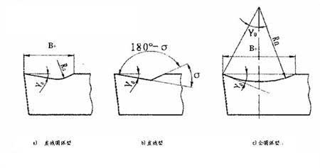
Figure 5 The shape of the chip breaker
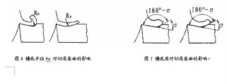
(1)The straight arc-shaped chipbreaker (see Figure 5a) is connected by a straight line and a circular arc. The straight portion constitutes the rake face of the cutter, and the radius Rn of the groove bottom has a certain influence on the curling and deformation of the swarf. When Rn is small, the swarf curl radius is small, and the swarf deformation is large; when Rn is large, the swarf curl radius is large, and the swarf deformation is small. (See Figure 6). Under medium depth of cut (cutting depth ap=2~6mm), generally optional
Rn = (0.4 to 0.7) B , B is the width of the chip breaker.
(2)The linear chipbreaker (see Figure 5b) is formed by the intersection of two straight lines. The bottom angle of the groove is 180°-σ (σ is called the chipboard wedge angle), and the groove bottom angle (180°-σ) replaces the action of the arc Rn. When the bottom angle of the groove is small, the curling radius of the swarf is small, and the swarf deformation is large; when the groove bottom angle is large, the curling radius of the swarf is large (see FIG. 7). In the medium depth of cut, the chipboard wedge angle is generally selected from 60 ° to 70 °.
The above two shape chipbreakers are suitable for processing carbon steel and alloy structural steel, and the front angle is generally γ. In the range of 5-15 °.
3. The main parameter groove width B, the groove bottom arc radius Rn and the rake angle γ of the full arc type chip breaker (see Fig. 5c). The relationship between:
(See Figure 5C)
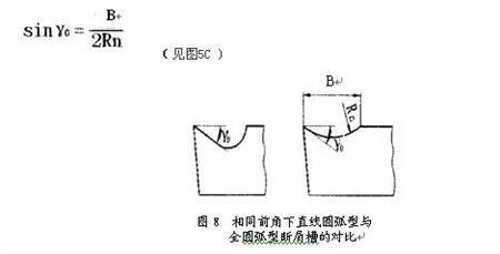
When cutting high-plastic materials such as copper and stainless steel, a full arc-shaped chipbreaker is often used. Because of the high plasticity material, the tool rake angle is chosen to be relatively large (γ0=25°-30°). The same large front angle, the full arc cutting chip cutter has a relatively strong cutting edge, and the groove is also shallow, which is convenient for swarfs, so it is more practical (see Figure 8).
(2) the width of the chip breaker
The chip breaker width B is related to the feed rate f and the depth of cut ap. When the feed amount f is increased, the cutting thickness is increased, and the width of the chip breaker should be widened accordingly; The cutting depth is large and the groove should be properly widened.
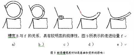
Fixed, the effect of the change in the width B of the chip breaker on chip curling and deformation. Figure 9a shows that the groove width and the feed amount are basically adapted, and the chips are curled and deformed to break into a C shape; Figure 9b is that the groove is not wide enough, the chip has a small curl radius, large deformation, and is broken into a short C shape or a chipped piece after collision; In Figure 9c, the groove is too narrow, and the chips are squeezed into small rolls. The blockage is difficult to flow out in the groove, causing the chips to even damage the cutting edge; Figure 9d, e is the groove is too wide, the chip curl radius is too large, deformation is not enough. Not easy to break. Sometimes it does not even flow through the bottom of the groove to form freely formed strips.
If the width of the chipbreaker is initially selected by the feed amount, roughly speaking, for cutting carbon steel, the relationship between the width B and the feed amount f is about B=10f; When cutting alloy steel, in order to increase chip deformation, B = 7f can be taken.
The width B of the chip breaker should also be adapted to the depth of cut ap. Generally, the slot width B can also be selected roughly according to ap. When ap is large, B should also be larger; When ap is small, then B should be reduced appropriately. Because when the depth of cut is large and the groove is too narrow, the chips are wide and are not easy to curl in the groove, so that the chips often do not flow into the bottom of the groove and form strips on their own; When the depth of cut is small and the groove is too wide, the chips are narrow, the flow is relatively free, the deformation is insufficient, and it is not easy to break.


