Process Analysis of Compound Machining of Thin-walled Casing Parts by Five-axis Milling Turning
Keywords: five axis milling machining ring thin-wall casing
High-performance aircraft engines employ a large number of integral, thin-walled complex structures and difficult-to-machine material parts. The use of a complex overall thin-walled structure reduces the weight of the engine components and helps to increase the engine thrust-to-weight ratio, but also increases the processing difficulty. The outer surface and mounting seat of thin-walled casing with complex structure of aero-engine need five-axis linkage milling, and the inner surface and front and back mounting edges need NC turning. The positioning holes and connecting holes on the front and rear mounting sides need to be drilled, expanded, twisted and hinged. In the process of thin-wall machine boring and the process of different processes, there is deformation phenomenon, which causes the subsequent processing process to be clamped and difficult to find, which seriously affects the processing quality and efficiency of the casing. Since the birth of the world's first CNC machine tool in the United States in 1952, there have been more and more types of CNC machine tools, more and more powerful functions and multi-functions. The composite machining center has been widely used in the aviation industry, solving the problem of complex machining of complex structures and difficult-to-machine materials. Five-coordinate milling turning compound machining center has the functions of drilling, boring, milling and turning. It is equipped with a 40-position tool magazine with automatic tool change processing and equipped with Renishaw infrared probes and online measuring systems. It can realize the multi-process composite processing of the machine part, avoiding the error caused by the secondary clamping and alignment of the thin-wall machine, and improving the processing automation.
In recent years, in the field of aeroengine casing processing, milling-turning compound processing technology has been widely used abroad. The production efficiency is greatly improved, the processing flow is reduced, the processing cycle is shortened, the introduction of other equipment factories is saved, and the probability of waiting and crashing of different equipment is reduced. At the same time, it improves the quality of parts processing, ensures the consistency of milling, turning and drilling, and reduces the cost of cutting tools. Domestic 5-axis milling machine compound machining center equipment, there are mature cases of the application of milling machine compound processing technology in domestic aero-engine casing. In this paper, the application of milling-turning compound machining technology in Aeroengine thin-walled casing processing is introduced, which is based on the five-coordinate milling-turning compound machining center and the whole annular thin-walled casing. It mainly includes:
Five-coordinate milling machine compound machining center introduction, integral ring thin-walled casing process analysis. The planning of the process route of the milling and turning combined machining technology, the preparation of the NC program for the milling and turning combined machining, and the verification process of the virtual simulation processing.
Processing Technology Analysis of Integral Ring Thin-walled Casing
1. Part structure
The external casing is a component of the aircraft engine high-pressure compressor casing and belongs to a typical overall thin-walled ring casing. Its inner surface is a rotating body, which is finished by machining; The outer surface has embossed islands of uniform distribution, which are completed by milling; Installation edges and radial holes are distributed on the front, back and radial surfaces of the casing. The structure of the casing fully meets the requirements of milling-turning compound processing technology. The main dimensions of the part are: the maximum outer diameter is φ468.1mm, The minimum inner diameter is φ433.4mm, Height 69.75mm, Minimum wall thickness (1+0.2) mm, The flatness of the end face is 0.03 mm, and the minimum position of the end face and the radial hole is φ0.03 mm, as shown in Fig. 1.
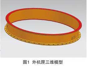
Three-dimensional Diagram Model of Ring Thin-walled Casing
2. Part material
According to the requirements of the design drawings, the material grade is 1Cr11Ni2W2MoV, which is austenitic stainless steel. The design requires hardness of HB311~352, and its strength can be adjusted according to the process heat treatment, but the heat resistance and corrosion fatigue are superior to other stainless steels.
3. processing difficulties analysis
The outer casing of the minimum wall thickness of only 1mm, the end position of the holes relative to the end and stop opening only for φ0.03mm, which is a typical integral annular thin wall machine. The difficulty in processing this part is how to ensure the position of φ0.03mm required by the design. If the part is deformed after machining, the end face and the stop of the part are more than 0.015 mm, and the position of the positioning hole which is corrected by the secondary clamping is difficult to ensure.
Findings from Process Analysis of Outer Casing.
Due to the thin wall thickness of the machine, it is a typical integral ring machine, which will produce a certain degree of deformation after machining. Because the casing wall thickness is thin, it belongs to the typical integral annular casing, which will produce a certain degree of deformation after turning. Usually, after the processing of the casing, the processing of the front and rear mounting edges and the radial mounting seat holes is arranged, which will cause the difficulty of the second clamping and aligning of the parts. The error of the secondary clamping alignment will affect the position of the precision positioning hole processing, and it is difficult to ensure the processing quality.
The processing concept of the milling and turning compound technology is “one-time clamping, machining, and complete all surface and hole machining of the parts”. That is, the inner surface machining and the outer surface milling processing of one part on one machine and the hole machining on the surface of the part can be completed on one machine tool, which can ensure the high precision assembly of the parts. Therefore, according to the structural characteristics and technical requirements of the integral thin-walled annular casing, the compound processing scheme of the outer casing milling machine is formulated. The end face and the end face reference and the mouth surface are processed through a single process and a single clamping. Avoid errors caused by secondary clamping, shorten the process route, improve processing efficiency, and ensure processing quality.
2. milling turning composite processing route
The principle of milling the machining process:
Try to complete the machining of parts in multiple directions in one setup.
According to the above-mentioned milling and composite process preparation method and principle, the process route of the part is determined as:
0 blank material chart -—15 Ultrasound inspection —20 rough turning backend —25 rough turning front end —30 drill collar front angle hole—35 rough milling boss — 40 deburring—45 Stable processing—50 repair front end reference—55 Semi-finished turning rear end—60 Semi-finished front end and fine angle hole—65 Finishing rear end, milling boss and drill collar face-70 finishing distal end face and Boring—75 Deburring and Clamping Surface—80 Mark —83 Intermediate test—85 Cleaning —90 fluoroscopy—95 cleaning—100 Final inspection.
From the point of view of the technological route, the rough processing of this part is on the CNC vertical lathe. Considering that there is no positioning groove for the four-jaw chuck on the milling workbench, it is impossible to carry out roughing in the milling machining center. For the precision of the machine, the roughing cannot be performed on the milling equipment. Starting from 30 processes, the rest of the machining processes are all carried out in the milling machine center, a total of 7 turnovers to achieve rough milling, semi-finishing, finishing parts.
High-performance aircraft engines employ a large number of integral, thin-walled complex structures and difficult-to-machine material parts. The use of a complex overall thin-walled structure reduces the weight of the engine components and helps to increase the engine thrust-to-weight ratio, but also increases the processing difficulty. The outer surface and mounting seat of thin-walled casing with complex structure of aero-engine need five-axis linkage milling, and the inner surface and front and back mounting edges need NC turning. The positioning holes and connecting holes on the front and rear mounting sides need to be drilled, expanded, twisted and hinged. In the process of thin-wall machine boring and the process of different processes, there is deformation phenomenon, which causes the subsequent processing process to be clamped and difficult to find, which seriously affects the processing quality and efficiency of the casing. Since the birth of the world's first CNC machine tool in the United States in 1952, there have been more and more types of CNC machine tools, more and more powerful functions and multi-functions. The composite machining center has been widely used in the aviation industry, solving the problem of complex machining of complex structures and difficult-to-machine materials. Five-coordinate milling turning compound machining center has the functions of drilling, boring, milling and turning. It is equipped with a 40-position tool magazine with automatic tool change processing and equipped with Renishaw infrared probes and online measuring systems. It can realize the multi-process composite processing of the machine part, avoiding the error caused by the secondary clamping and alignment of the thin-wall machine, and improving the processing automation.
In recent years, in the field of aeroengine casing processing, milling-turning compound processing technology has been widely used abroad. The production efficiency is greatly improved, the processing flow is reduced, the processing cycle is shortened, the introduction of other equipment factories is saved, and the probability of waiting and crashing of different equipment is reduced. At the same time, it improves the quality of parts processing, ensures the consistency of milling, turning and drilling, and reduces the cost of cutting tools. Domestic 5-axis milling machine compound machining center equipment, there are mature cases of the application of milling machine compound processing technology in domestic aero-engine casing. In this paper, the application of milling-turning compound machining technology in Aeroengine thin-walled casing processing is introduced, which is based on the five-coordinate milling-turning compound machining center and the whole annular thin-walled casing. It mainly includes:
Five-coordinate milling machine compound machining center introduction, integral ring thin-walled casing process analysis. The planning of the process route of the milling and turning combined machining technology, the preparation of the NC program for the milling and turning combined machining, and the verification process of the virtual simulation processing.
Processing Technology Analysis of Integral Ring Thin-walled Casing
1. Part structure
The external casing is a component of the aircraft engine high-pressure compressor casing and belongs to a typical overall thin-walled ring casing. Its inner surface is a rotating body, which is finished by machining; The outer surface has embossed islands of uniform distribution, which are completed by milling; Installation edges and radial holes are distributed on the front, back and radial surfaces of the casing. The structure of the casing fully meets the requirements of milling-turning compound processing technology. The main dimensions of the part are: the maximum outer diameter is φ468.1mm, The minimum inner diameter is φ433.4mm, Height 69.75mm, Minimum wall thickness (1+0.2) mm, The flatness of the end face is 0.03 mm, and the minimum position of the end face and the radial hole is φ0.03 mm, as shown in Fig. 1.
Three-dimensional Diagram Model of Ring Thin-walled Casing
According to the requirements of the design drawings, the material grade is 1Cr11Ni2W2MoV, which is austenitic stainless steel. The design requires hardness of HB311~352, and its strength can be adjusted according to the process heat treatment, but the heat resistance and corrosion fatigue are superior to other stainless steels.
3. processing difficulties analysis
The outer casing of the minimum wall thickness of only 1mm, the end position of the holes relative to the end and stop opening only for φ0.03mm, which is a typical integral annular thin wall machine. The difficulty in processing this part is how to ensure the position of φ0.03mm required by the design. If the part is deformed after machining, the end face and the stop of the part are more than 0.015 mm, and the position of the positioning hole which is corrected by the secondary clamping is difficult to ensure.
Overall ring machine boring and milling turning composite processing scheme
1. Overall planFindings from Process Analysis of Outer Casing.
Due to the thin wall thickness of the machine, it is a typical integral ring machine, which will produce a certain degree of deformation after machining. Because the casing wall thickness is thin, it belongs to the typical integral annular casing, which will produce a certain degree of deformation after turning. Usually, after the processing of the casing, the processing of the front and rear mounting edges and the radial mounting seat holes is arranged, which will cause the difficulty of the second clamping and aligning of the parts. The error of the secondary clamping alignment will affect the position of the precision positioning hole processing, and it is difficult to ensure the processing quality.
The processing concept of the milling and turning compound technology is “one-time clamping, machining, and complete all surface and hole machining of the parts”. That is, the inner surface machining and the outer surface milling processing of one part on one machine and the hole machining on the surface of the part can be completed on one machine tool, which can ensure the high precision assembly of the parts. Therefore, according to the structural characteristics and technical requirements of the integral thin-walled annular casing, the compound processing scheme of the outer casing milling machine is formulated. The end face and the end face reference and the mouth surface are processed through a single process and a single clamping. Avoid errors caused by secondary clamping, shorten the process route, improve processing efficiency, and ensure processing quality.
2. milling turning composite processing route
The principle of milling the machining process:
Try to complete the machining of parts in multiple directions in one setup.
According to the above-mentioned milling and composite process preparation method and principle, the process route of the part is determined as:
0 blank material chart -—15 Ultrasound inspection —20 rough turning backend —25 rough turning front end —30 drill collar front angle hole—35 rough milling boss — 40 deburring—45 Stable processing—50 repair front end reference—55 Semi-finished turning rear end—60 Semi-finished front end and fine angle hole—65 Finishing rear end, milling boss and drill collar face-70 finishing distal end face and Boring—75 Deburring and Clamping Surface—80 Mark —83 Intermediate test—85 Cleaning —90 fluoroscopy—95 cleaning—100 Final inspection.
From the point of view of the technological route, the rough processing of this part is on the CNC vertical lathe. Considering that there is no positioning groove for the four-jaw chuck on the milling workbench, it is impossible to carry out roughing in the milling machining center. For the precision of the machine, the roughing cannot be performed on the milling equipment. Starting from 30 processes, the rest of the machining processes are all carried out in the milling machine center, a total of 7 turnovers to achieve rough milling, semi-finishing, finishing parts.
PREVIOUS:NONE
NEXT:DMG Five-axis Milling and Turning Complex Machining Ultra-thin Outer Casing
NEXT:DMG Five-axis Milling and Turning Complex Machining Ultra-thin Outer Casing


