China 5-axis Machining Supplier
What is 5-axis machining? Functions and application settings of 5-axis machining:
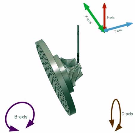
5-axis machining is a mode of CNC machining. Linear interpolation motion using any 5 coordinates among X, Y, Z, A, B, and C.In other words, five axes refer to the three moving axes of x, y, and z plus any two rotating axes. Compared with the common 3-axis (x, y, z three degrees of freedom) machining, 5-axis machining refers to the processing of parts with complex geometric shapes, and the machining tool needs to be positioned and connected in 5 degrees of freedom.
5-axis linkage means that there are at least 5 coordinate axes (3 linear coordinates and 2 rotation coordinates) on a machine tool, and can be coordinated for processing under the control of a computer numerical control (CNC) system.
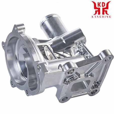
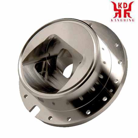
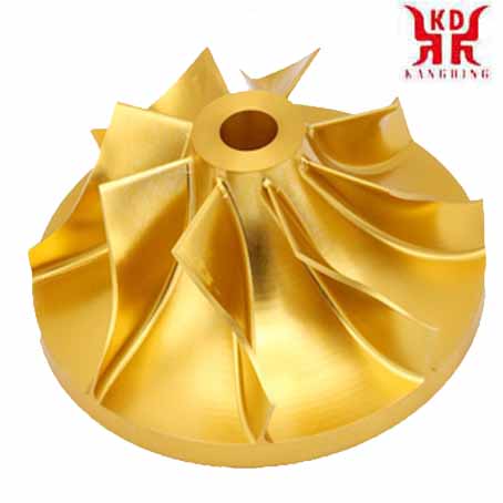
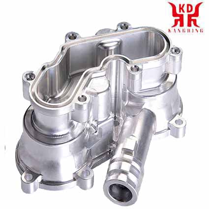
The five-axis linkage CNC machine tool is a machine tool with high technology content and high precision. It is specially used for processing body parts, turbine parts and impellers with free-form surfaces. The five-axis machine tool can process different sides of the workpiece without changing the position of the workpiece on the machine tool, which can greatly improve the processing efficiency of prismatic parts. This kind of machine tool system has a pivotal influence on a country's aviation, aerospace, military, scientific research, precision equipment, high-precision medical equipment and other industries.
But do you really understand five-axis machining?
Development of 5-axis technology
For decades, it has been widely believed that five-axis CNC machining technology is the only means to process continuous, smooth, and complex curved surfaces. Once people encounter unsolvable problems in the design and manufacture of complex curved workpieces, they will turn to five-axis machining technology. but. . .Five-axis linkage CNC is the most difficult and most widely used technology in CNC technology. It integrates computer control, high-performance servo drive and precision machining technology, and is used in the efficient, precise and automated machining of complex curved surfaces. Internationally, the five-axis linkage numerical control technology is regarded as a symbol of the automation technology level of a country's production equipment. Because of its special status, it is especially important for aviation, aerospace, military industry, and technical complexity. Industrial developed countries have always implemented the export license system for the five-axis CNC system as a strategic material.
Compared with three-axis CNC machining, from the perspective of technology and programming, the use of 5-axis CNC machining for complex curved surfaces has the following advantages:
(1) Improve processing quality and efficiency
(2) Expand the process range
(3) Meet the new development direction of compound processing
However, due to interference and position control of the tool in the machining space for 5-axis CNC machining, its CNC programming, process design and machine tool structure are far more complex than 3-axis machine tools. Therefore, the five-axis is easy to say, but it is really difficult to realize it! In addition, the correct operation of the application is more difficult!
When it comes to five-axis, I have to talk about the true and false five-axis. The difference between true and false 5-axis is mainly whether there is RTCP function. To this end, I specifically searched for the meaning of this word!
RTCP, explain, Fidia's RTCP is the abbreviation of "Rotational Tool Center Point", which literally means "rotating tool center". The industry tends to slightly escape it as "turn around the tool center", and some people literally translate it as "rotating tool center programming". In fact, this is just the meaning of RTCP. The RTCP of PA is the abbreviation of the first few words of "Real-time Tool Center Point rotation". Heidenhain refers to the similar so-called upgrade technology as TCPM, which is the abbreviation of "Tool Centre Point Management", tool center point management. Other manufacturers call the similar technology TCPC, which is the abbreviation of "Tool Center Point Control", which is the tool center point control.
From the literal meaning of Fidia's RTCP, assuming that the RTCP function is performed manually, the tool center point and the actual contact point between the tool and the workpiece surface remain unchanged. At this point in time, the tool center point falls on the normal of the actual contact point between the tool and the workpiece surface. The tool holder rotates around the tool center point. For tools with a ball head, the tool center point is the target trajectory point of the NC code. In order to achieve the purpose of simply rotating the tool holder around the target trajectory point (i.e. the tool center point) when executing the RTCP function, it is necessary to compensate for the offset of the linear coordinates of the tool center point caused by the rotation of the tool holder in real time . In this way, the center of the tool and the actual contact point between the tool and the workpiece surface can be kept unchanged. Changing the angle between the tool holder and the normal at the actual contact point of the tool and the workpiece surface can achieve the best cutting performance of the ball end tool and effectively avoid interference. Therefore, RTCP seems to be more on the tool center point (i.e. the target trajectory point of the numerical control code) to deal with the change in the rotation coordinate.
Five-axis machine tools and CNC systems that do not have RTCP must rely on CAM programming and post-processing. The tool path is planned in advance. For the same part, if the machine tool is changed or the tool is changed, CAM programming and post-processing must be performed again, so it can only be called a fake five-axis. Many five-axis CNC machine tools and systems belong to this type of fake five-axis. Of course, it is understandable that people insist on calling it five-axis machining, but this (fake) five-axis is not the other (true) five-axis!
Therefore, experts in the industry were consulted. In short, the real five-axis is the linkage of the five-axis, the fake five-axis may be the 5-axis 3-linkage, and the other 2 axes only play a positioning function!
This is a popular saying, not a normative one. Generally speaking, there are two types of five-axis machine tools: one is five-axis linkage, that is, all five axes can be linked at the same time. The other is five-axis positioning processing, which is actually five-axis three linkage:
That is, the two rotating shafts are rotated and positioned, and there is only 3-axis linkage processing. This kind of five-axis machine tool commonly known as 3+2 mode can also be understood as a fake five-axis machine.
The structure of five-axis CNC machine tools
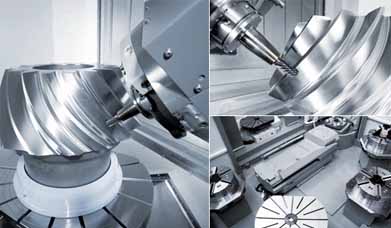
In the mechanical design of 5-axis machining centers, machine tool manufacturers have always been unremittingly committed to developing new motion modes to meet various requirements. In summary, there are various types of five-axis machine tools currently on the market, although their mechanical structures are in various forms. But there are mainly the following forms:Two rotating coordinates directly control the direction of the tool axis (5 axes in the form of double pendulum heads)
The two coordinate axes are at the top of the tool, but the rotation axis is not perpendicular to the linear axis (5 axis of pendulous head type)
Two rotating coordinates directly control the rotation of the space (5-axis in the form of a double turntable)
The two coordinate axes are on the workbench, but the rotation axis is not perpendicular to the linear axis (5 axes for the vertical workbench)
Two rotating coordinates, one acting on the tool and the other acting on the workpiece (5 axes in the form of one pendulum and one rotation)
Having seen these five-axis machine tools, I believe we should understand how the five-axis machine tools move.
Difficulties and resistances in developing five-axis CNC technology
Everyone has long recognized the superiority and importance of five-axis CNC technology. But so far, the application of five-axis CNC technology is still limited to a few well-funded factories, and there are still unsolved problems.Here are some difficulties and resistances to see if they correspond to your situation?
Five-axis CNC programming is abstract and difficult to operate
This is a headache that every traditional CNC programmer feels deeply. Three-axis machine tools only have linear coordinate axes, while five-axis CNC machine tools have various structures;
The same NC code can achieve the same processing effect on different three-axis CNC machine tools, but the NC code of a certain five-axis machine tool cannot be applied to all types of five-axis machine tools. In addition to linear motion, CNC programming must coordinate the calculation of rotary motion. Such as rotation angle travel inspection, non-linear error check, tool rotation calculation, etc. The amount of information processed is huge, and CNC programming is extremely abstract.
The operation and programming skills of 5-axis CNC machining are closely related:
If the user adds special functions to the machine tool, the programming and operation will be more complicated. Only by repeated practice, programming and operating personnel can master the necessary knowledge and skills. The lack of experienced programming and operators is a major obstacle to the popularization of five-axis CNC technology.
Many manufacturers have purchased 5-axis CNC machine tools from abroad. Due to inadequate technical training and services, it is difficult to realize the inherent functions of 5-axis CNC machine tools, and the utilization rate of the machine tools is very low. In many occasions, the application is not as good as using a 3-axis machine tool.
Very strict requirements for NC interpolation controller and servo drive system
The movement of a 5-axis machine tool is a combination of the movement of the five coordinate axes. The addition of rotating coordinates will not only increase the burden of interpolation calculations, but also the small errors of the rotating coordinates will greatly reduce the processing accuracy. Therefore, the controller is required to have higher arithmetic accuracy.The motion characteristics of 5-axis machine tools require the servo drive system to have good dynamic characteristics and a large speed range.
5-axis CNC NC program verification is particularly important
To improve the efficiency of machining, it is urgent to eliminate the traditional "trial cutting method" verification method. In the 5-axis CNC machining, the verification of the NC program has also become very important, because the workpiece usually processed by the 5-axis CNC machine tool is very expensive. And collision is a common problem in five-axis CNC machining: the tool cuts into the workpiece; The tool collides with the workpiece at a very high speed; the tool collides with the machine tool, fixture and other equipment within the processing range; the moving part on the machine tool collides with the fixed part or the workpiece. In five-axis CNC, collisions are difficult to predict, and the calibration program must conduct a comprehensive analysis of the machine kinematics and control system.If the CAM system detects an error, the tool path can be processed immediately; However, if an NC program error is found during processing, the tool path cannot be modified directly as in 3-axis CNC. On a three-axis machine tool, the machine operator can directly modify the tool radius and other parameters. In 5-axis machining, the situation is not so simple, because the change of the tool size and position has a direct effect on the trajectory of the subsequent rotation.
Tool radius compensation
In the NC program of 5-axis linkage, the tool length compensation function is still valid, but the tool radius compensation is invalid. When using cylindrical milling cutters for contact forming milling, different programs need to be programmed for cutters of different diameters. The current popular CNC systems are unable to complete the tool radius compensation, because the ISO file does not provide enough data to recalculate the tool position. The user needs to change the tool frequently or adjust the exact size of the tool when performing CNC machining. According to the normal processing procedure, the tool path should be sent back to the CAM system for recalculation. As a result, the efficiency of the entire processing process is very low.In response to this problem, Norwegian researchers are developing a temporary solution, called LCOPS, low-consumption optimal production strategy). The data required for tool path correction is sent to the CAM system by the CNC application, and the calculated tool path is directly sent to the controller. LCOPS requires a third party to provide CAM software, which can be directly connected to the CNC machine tool, during which the CAM system file is transmitted instead of the ISO code. The final solution to this problem depends on the introduction of a new generation of CNC control system, which can recognize workpiece model files in common formats (such as STEP, etc.) or CAD system files.
Post processor
The difference between a 5-axis machine tool and a 3-axis machine tool is that it also has two rotating coordinates. The tool position is transformed from the workpiece coordinate system to the machine coordinate system, and several coordinate transformations are required in the middle. Using the popular post processor generator on the market, you only need to input the basic parameters of the machine tool to generate the post processor of the three-axis CNC machine tool. For five-axis CNC machine tools, there are currently only some improved post processors. The post processor of the five-axis CNC machine tool needs further development.When three-axis simultaneous machining, the position of the workpiece origin on the machine tool table does not need to be considered in the tool trajectory, and the post processor can automatically process the relationship between the workpiece coordinate system and the machine coordinate system. For five-axis simultaneous machining: For example, when machining on a five-axis milling machine, the position and size of the workpiece on the C turntable and the position and size between the B and C turntables must be considered when generating the tool path. Workers usually spend a lot of time dealing with these positional relationships when clamping workpieces. If the post processor can process these data, the installation of the workpiece and the processing of the tool path will be greatly simplified; Just clamp the workpiece on the worktable, measure the position and direction of the workpiece coordinate system, input these data into the post processor, and post-process the tool path to get the appropriate NC program.
Non-linear errors and singularity problems
Due to the introduction of rotating coordinates, the kinematics of a five-axis CNC machine tool is much more complicated than that of a three-axis machine tool. The first problem related to rotation is nonlinear error. The non-linear error should be attributed to the programming error, which can be controlled by reducing the step distance. In the pre-calculation stage, the programmer cannot know the magnitude of the nonlinear error. Only after the machine tool program is generated by the post processor can the nonlinear error be calculated. Tool path linearization can solve this problem. Some control systems can linearize the tool trajectory while processing, but it is usually linearized in the post processor.Another problem caused by the rotating shaft is singularity. If the singular point is at the extreme position of the rotating shaft, a small oscillation near the singular point will cause the rotating shaft to flip by 180°, which is quite dangerous.


