CNC 5 axis milling of airfoil airfoil parts
The airfoil typ parts has a wing-shaped section and a three-dimensional twisted space. It has a wide range of applications in axial flow turbo compressors, and its manufacturing has been generally carried out using a five-coordinate linkage CNC machine tool.
I. the processing method overview
The processing of the airfoil parts root by the five-axis machining center. It is usually carried out in the manner shown in Figure 1. The airfoil parts blank is clamped on the A-axis of the rotary table for 360° rotation, and the spindle milling head is swung in the C-axis direction. During the actual machining process, the pneumatic tip tops the tightened. The processing of airfoil airfoil parts can be completed in three steps: roughing, semi-finishing and finishing. The best way to finish the airfoil airfoil parts is by five-axis linkage, which is done by high-speed spiral cutting. This type of machining is the most efficient and the airfoil parts shape is also ideal.
The airfoil parts portion is usually machined by a face milling cutter, and the face milling cutter has a high cutting efficiency, but the face milling cutter cannot have a fixed swing angle in the C-axis direction. To avoid interference when machining to the root portion, the leaf shape near the root portion is usually machined with a ball end mill. Deviate a fixed angle in the C-axis direction to avoid interference between the tool and the airfoil parts root. This deflection angle in the C-axis direction is too small to avoid interference, and too large may cause interference at the airfoil parts shape on the other side. This is especially important for moving airfoil parts with a high degree of distortion.
II. data preparation
The axial flow compressor airfoil parts in the turbomachinery and the TRT axial flow energy recovery expansion airfoil parts shape. The representation of the design pattern to the profile is usually the airfoil parts data of several sections, which may be a spatial lattice or a multi-segment arc. The data must be pre-processed. The main work content is smoothing, rotation, and translation, so that the design coordinate system is combined with the machine coordinate system, that is, the design reference and the processing reference are unified. The airfoil parts is processed by high-speed spiral cutting method, and the design of the airfoil parts profile smoothness and continuity is very high. The airfoil parts profile (back arc surface, inner arc surface, rounded corners of the inlet and outlet) must not have sharp points, vertices, and joints. Otherwise, under high-speed cutting conditions, the tool can easily generate large vibrations in an instant, causing equipment accidents. Another case where the leaf shape is not smooth is in the modeling process, although the profile of each section is a smooth continuous function curve. However, when forming a three-dimensional shape along the axis, the profile is not smooth, and there is a "wavy" undulation in the middle, which is usually corrected by adjusting the reference of each section.
In the case where the data in the same section cannot form a smooth spline, the original data must be modified. The specific method is to take n points on the section curve, take a point where the curvature is large, and take a point where the curvature is small, and make the normal of these points. As shown in Figure 2 and Figure 3. In Figure 3, the normal direction of each point of the smooth continuous curve changes gently. Figure 2. Cross-sectional curves formed by poor raw data. The normal direction of the different nodes changes drastically, and the section curve is obviously not smooth. If the three-dimensional space is generated by such a section curve, the airfoil parts profile is uneven and cannot be realized during processing.
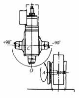
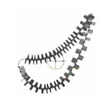
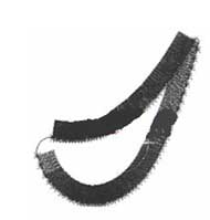
figure 1 airfoil parts, blade root processing methods figure 2 Sectional curve formed by raw data image 3 Section curve after modifying the data
III. Mathematical modeling
The data of each cross-section of the airfoil type parts is expressed as a uniform distribution along the circumferential direction of the wing, and the axial direction is given along the straight-line bus.
Based on the above, the first step of airfoil parts modeling is performed in a two-dimensional plane. Each section forms a closed curve in the plane, each curve having a fixed position in the length of the airfoil parts. Rotate each section first in a fixed position and then translate. The leaf shape of a airfoil parts generally has two forms: First, it consists of a spline curve, and the inlet and outlet sides have two arc transitions respectively; The second is a closed curve composed of multiple arcs. The following points must be noted when modeling.
1, The section curve of the leaf type must be smooth and continuous closed
For the case where the airfoil curve is not closed. For example, if the arc of the inlet and outlet sides is not tangent to the curve of the inner back curve, the position of the center of the arc should be changed. Either change the radius of the arc center or adjust the end point of the inner back curve to ensure that the chord length of the airfoil parts does not change.
In order to ensure that the chord length is constant, a straight line tangent to the chord length and tangent to the arc of the known intake side (or venting edge) can be made, and then the end points of the two inner back arc curves are respectively made, and the inner back is A straight line tangent to the arc curve. This forms three straight lines, making a circle tangent to the three straight lines. This circle is tangent to the inner back arc, which plays a smooth transition and ensures the chord length.
2, Tool overcutting Calculation
There are two ways to avoid tool overcutting, ie changing the tool diameter or changing the cutting angle. For airfoil parts profiles with large curvature, overcutting is more likely to occur. For the convex surface machining, the overcut phenomenon is not easy to occur when the knife cluster is cut along the normal surface of the profile; For the concave curved surface, the cutter cluster is still cut along the surface normal, and the overcut is caused by the influence of the radius of curvature. In this case, the method of avoiding tool overcutting should preferably change the tool radius. Calculating tool diameter and cutting angle while modeling can greatly improve programming efficiency. As shown in Figure 5, the method is: On the closed airfoil parts profile curve that has been modeled, take n points evenly, and then at the first point, define an imaginary tool and an imaginary cutting angle. The tool is sequentially passed through each point on the section at a determined cutting angle in a sequential cycle, while observing whether there is an overcut phenomenon, and if so, modifying the tool diameter and the cutting angle. Since the cutting condition observed at this time is in a two-dimensional space, and only for a certain section, it does not reflect the actual three-dimensional processing, so further technical processing is required. That is, the adjacent two airfoil parts sections are projected in the same plane. If the section distance is larger than the tool diameter, the tool and the adjacent two airfoil parts sections are not overcut on the projection map, then the imaginary tool diameter and the cutting angle can be considered appropriate. In order to improve the cutting efficiency, a large diameter cutter is used as much as possible without overcutting.
3, Establishment of coordinate system
To machine any part on a CNC machine, create a three-dimensional coordinate system. In actual machining, a reasonable coordinate system can simplify programming and facilitate tool setting. It is usually necessary to ensure that the design basis is aligned with the machining reference, and the X coordinate system is established on the airfoil parts axis as much as possible on the machining center. That is, the X axis coincides with the axis of the airfoil parts, which is equivalent to determining the origin of the Y axis and the Z axis. For rotor airfoil parts, the airfoil parts leaf type has a smooth connection with the airfoil parts root, called the transition arc. The part of the transition arc located at the root of the airfoil parts is usually a cylindrical surface or a spherical surface, and the origin of the X-axis can be determined on the center of the cylinder or the sphere. For the vane of the rotor, the portion of the transition arc at the root of the airfoil parts may be cylindrical or spherical, or it may be a bevel. If it is a cylindrical surface or a spherical surface, the X-axis origin is determined in the same way as the moving airfoil parts; If it is a bevel, the method of determining the origin of the X-axis can be determined according to the condition of the tool.
4, Leaf extension and interception
In the usual case, in the design of the airfoil parts, only the list curve data of several sections is given. The actual leaf shape may be longer than the leaf shape determined by the given section, and may be shorter than it. If it is the first case, the leaf type should be extended. If it is the second case, the leaf type should be intercepted. Relatively speaking, the interception of the leaf type should be handled better. Simply use a flat or compound surface to intercept the airfoil parts at a specific location to obtain a new section, and use the data from the new section to form the desired leaf-shaped entity. For the extension of the leaf type, it is also necessary to perform a smoothing process on the leaf shape. The smoothness of the line method is only a plane curve, and the leaf shape is a space curve after extension. That is, the projection curves in two or three coordinate planes are respectively smoothed. In fact, it is generally only necessary to project the spatial curve onto two planes, and smooth the two plane curves obtained separately, and then synthesize the spatial curve (that is, three-dimensional processing as two-dimensional). Practice has proved that, in general, the projection curve of a spatial curve in each coordinate plane is smooth, and the spatial curve is also smooth.
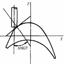
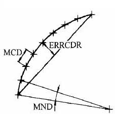
Figure 5 Tool overcut calculation Figure 6 Adjusting the parameters of the fitted curve
IV. Determination of cutting parameters
1, the parameters of the fit curve
When machining a blade profile, it is necessary to combine the motions of the three linear axes and the two rotary axes to achieve the desired trajectory of the contour.
In the actual calculation process, the three parameters shown in Figure 6 can be appropriately adjusted to meet the technical conditions of the blade.
MND is used to determine the angle at which the leaf shape error is controlled. Each section of the airfoil curve can be divided into an infinite number of segments, and the curvature can be considered to be the same in each segment. The numerical value of MND directly determines the density of two adjacent points during interpolation. The smaller the value of MND, the denser the adjacent two points, and the higher the accuracy of the processed leaf shape.
MCD is to control the linear distance between two adjacent points, and ERRCDR is to control the chord difference between two adjacent points. As with the MND values, different MCD and ERRCDR values determine different densities.
Among the cutting parameters, since the space surface is generally processed by the line cutting method, the line spacing and the step size must be calculated or determined.
Line spacing S
The size of the line spacing S is directly related to the height of the residual groove on the processed surface. When it is large, the surface roughness is large. However, the S selection is too small, although it can improve the processing precision and reduce the difficulty of repairing the clamp, but the procedure is lengthy, the machining time is doubled, and the efficiency is lowered. Therefore, the selection of the line spacing S should be just right.
Cutting angle
When using a face milling cutter to machine the airfoil, the selection of the angle between the bottom surface of the face milling cutter and the tangential direction of the cutting point of the blade profile is very important. If it is improper, it is easy to produce overcutting. Determining the cutting angle is usually done in the actual production. The specific method is to make a contour map of a certain section of the blade as shown in FIG. 5 by drawing. Then, n points are uniformly taken on the cross section, and one of the points is an imaginary cutting point, and an arbitrary cutting angle is determined empirically. And make a tool cross-section, and then use the loop statement to make the tool go through n points, and observe whether there is over-cutting. If so, adjust the cutting angle and repeat the above work until there is no overcut.
Spindle speed, feed rate and depth of cut
The specific spindle speed, feed rate and depth of cut are determined by considering the material of the blade, the diameter of the tool, and the processing method. Five-coordinate blade machining centers typically use high-speed cutting.
V. Tool path simulation
Computer simulation processing simulation shows that it can also indicate overcutting and residual conditions;
At the same time, after the parameters of the machine body are programmed, the actual machining state of the machine tool holder can also be displayed, and the interference can be checked to avoid accidents.
VI. CNC machining blade root
The processing of the roots is an important part of the blade machining. Before this, the blade roots were usually machined on a blade milling machine using a forming tool. Since the processing of the airfoil can be done in one setup, the entire process from roughing to semi-finishing to finishing is completed. Moreover, the entire machining process is guaranteed by the numerical control program, and the processing of the blade root can also be completely adopted in this way. The structure of large TRT leaf roots is generally shown in Figure 9.
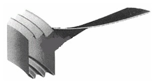
Figure 9 CNC turning and milling of TRT blade root
The processing of the leaf root is the same as the processing of the leaf type. It is usually divided into three parts: roughing and semi-finishing and finishing. In order to improve efficiency, roughing is usually carried out using a larger diameter die cutter, leaving only a margin of 0.2 mm for the root tooth profile. The main purpose of semi-finishing is to ensure that the finishing allowance is uniform, in addition to clearing the roots. According to the available data, a margin of 0.1 mm is reserved for finishing. Finishing is the most critical processing step. To improve efficiency and ensure surface roughness, the determination of cutting parameters is very important. In order to reduce the surface roughness value, finishing is usually performed in one direction. Although the one-way machining increases the idle travel of the tool and prolongs the machining time, the machining quality obtained by the one-way machining is guaranteed.
I. the processing method overview
The processing of the airfoil parts root by the five-axis machining center. It is usually carried out in the manner shown in Figure 1. The airfoil parts blank is clamped on the A-axis of the rotary table for 360° rotation, and the spindle milling head is swung in the C-axis direction. During the actual machining process, the pneumatic tip tops the tightened. The processing of airfoil airfoil parts can be completed in three steps: roughing, semi-finishing and finishing. The best way to finish the airfoil airfoil parts is by five-axis linkage, which is done by high-speed spiral cutting. This type of machining is the most efficient and the airfoil parts shape is also ideal.
The airfoil parts portion is usually machined by a face milling cutter, and the face milling cutter has a high cutting efficiency, but the face milling cutter cannot have a fixed swing angle in the C-axis direction. To avoid interference when machining to the root portion, the leaf shape near the root portion is usually machined with a ball end mill. Deviate a fixed angle in the C-axis direction to avoid interference between the tool and the airfoil parts root. This deflection angle in the C-axis direction is too small to avoid interference, and too large may cause interference at the airfoil parts shape on the other side. This is especially important for moving airfoil parts with a high degree of distortion.
II. data preparation
The axial flow compressor airfoil parts in the turbomachinery and the TRT axial flow energy recovery expansion airfoil parts shape. The representation of the design pattern to the profile is usually the airfoil parts data of several sections, which may be a spatial lattice or a multi-segment arc. The data must be pre-processed. The main work content is smoothing, rotation, and translation, so that the design coordinate system is combined with the machine coordinate system, that is, the design reference and the processing reference are unified. The airfoil parts is processed by high-speed spiral cutting method, and the design of the airfoil parts profile smoothness and continuity is very high. The airfoil parts profile (back arc surface, inner arc surface, rounded corners of the inlet and outlet) must not have sharp points, vertices, and joints. Otherwise, under high-speed cutting conditions, the tool can easily generate large vibrations in an instant, causing equipment accidents. Another case where the leaf shape is not smooth is in the modeling process, although the profile of each section is a smooth continuous function curve. However, when forming a three-dimensional shape along the axis, the profile is not smooth, and there is a "wavy" undulation in the middle, which is usually corrected by adjusting the reference of each section.
In the case where the data in the same section cannot form a smooth spline, the original data must be modified. The specific method is to take n points on the section curve, take a point where the curvature is large, and take a point where the curvature is small, and make the normal of these points. As shown in Figure 2 and Figure 3. In Figure 3, the normal direction of each point of the smooth continuous curve changes gently. Figure 2. Cross-sectional curves formed by poor raw data. The normal direction of the different nodes changes drastically, and the section curve is obviously not smooth. If the three-dimensional space is generated by such a section curve, the airfoil parts profile is uneven and cannot be realized during processing.
figure 1 airfoil parts, blade root processing methods figure 2 Sectional curve formed by raw data image 3 Section curve after modifying the data
III. Mathematical modeling
The data of each cross-section of the airfoil type parts is expressed as a uniform distribution along the circumferential direction of the wing, and the axial direction is given along the straight-line bus.
Based on the above, the first step of airfoil parts modeling is performed in a two-dimensional plane. Each section forms a closed curve in the plane, each curve having a fixed position in the length of the airfoil parts. Rotate each section first in a fixed position and then translate. The leaf shape of a airfoil parts generally has two forms: First, it consists of a spline curve, and the inlet and outlet sides have two arc transitions respectively; The second is a closed curve composed of multiple arcs. The following points must be noted when modeling.
1, The section curve of the leaf type must be smooth and continuous closed
For the case where the airfoil curve is not closed. For example, if the arc of the inlet and outlet sides is not tangent to the curve of the inner back curve, the position of the center of the arc should be changed. Either change the radius of the arc center or adjust the end point of the inner back curve to ensure that the chord length of the airfoil parts does not change.
In order to ensure that the chord length is constant, a straight line tangent to the chord length and tangent to the arc of the known intake side (or venting edge) can be made, and then the end points of the two inner back arc curves are respectively made, and the inner back is A straight line tangent to the arc curve. This forms three straight lines, making a circle tangent to the three straight lines. This circle is tangent to the inner back arc, which plays a smooth transition and ensures the chord length.
2, Tool overcutting Calculation
There are two ways to avoid tool overcutting, ie changing the tool diameter or changing the cutting angle. For airfoil parts profiles with large curvature, overcutting is more likely to occur. For the convex surface machining, the overcut phenomenon is not easy to occur when the knife cluster is cut along the normal surface of the profile; For the concave curved surface, the cutter cluster is still cut along the surface normal, and the overcut is caused by the influence of the radius of curvature. In this case, the method of avoiding tool overcutting should preferably change the tool radius. Calculating tool diameter and cutting angle while modeling can greatly improve programming efficiency. As shown in Figure 5, the method is: On the closed airfoil parts profile curve that has been modeled, take n points evenly, and then at the first point, define an imaginary tool and an imaginary cutting angle. The tool is sequentially passed through each point on the section at a determined cutting angle in a sequential cycle, while observing whether there is an overcut phenomenon, and if so, modifying the tool diameter and the cutting angle. Since the cutting condition observed at this time is in a two-dimensional space, and only for a certain section, it does not reflect the actual three-dimensional processing, so further technical processing is required. That is, the adjacent two airfoil parts sections are projected in the same plane. If the section distance is larger than the tool diameter, the tool and the adjacent two airfoil parts sections are not overcut on the projection map, then the imaginary tool diameter and the cutting angle can be considered appropriate. In order to improve the cutting efficiency, a large diameter cutter is used as much as possible without overcutting.
3, Establishment of coordinate system
To machine any part on a CNC machine, create a three-dimensional coordinate system. In actual machining, a reasonable coordinate system can simplify programming and facilitate tool setting. It is usually necessary to ensure that the design basis is aligned with the machining reference, and the X coordinate system is established on the airfoil parts axis as much as possible on the machining center. That is, the X axis coincides with the axis of the airfoil parts, which is equivalent to determining the origin of the Y axis and the Z axis. For rotor airfoil parts, the airfoil parts leaf type has a smooth connection with the airfoil parts root, called the transition arc. The part of the transition arc located at the root of the airfoil parts is usually a cylindrical surface or a spherical surface, and the origin of the X-axis can be determined on the center of the cylinder or the sphere. For the vane of the rotor, the portion of the transition arc at the root of the airfoil parts may be cylindrical or spherical, or it may be a bevel. If it is a cylindrical surface or a spherical surface, the X-axis origin is determined in the same way as the moving airfoil parts; If it is a bevel, the method of determining the origin of the X-axis can be determined according to the condition of the tool.
4, Leaf extension and interception
In the usual case, in the design of the airfoil parts, only the list curve data of several sections is given. The actual leaf shape may be longer than the leaf shape determined by the given section, and may be shorter than it. If it is the first case, the leaf type should be extended. If it is the second case, the leaf type should be intercepted. Relatively speaking, the interception of the leaf type should be handled better. Simply use a flat or compound surface to intercept the airfoil parts at a specific location to obtain a new section, and use the data from the new section to form the desired leaf-shaped entity. For the extension of the leaf type, it is also necessary to perform a smoothing process on the leaf shape. The smoothness of the line method is only a plane curve, and the leaf shape is a space curve after extension. That is, the projection curves in two or three coordinate planes are respectively smoothed. In fact, it is generally only necessary to project the spatial curve onto two planes, and smooth the two plane curves obtained separately, and then synthesize the spatial curve (that is, three-dimensional processing as two-dimensional). Practice has proved that, in general, the projection curve of a spatial curve in each coordinate plane is smooth, and the spatial curve is also smooth.
Figure 5 Tool overcut calculation Figure 6 Adjusting the parameters of the fitted curve
IV. Determination of cutting parameters
1, the parameters of the fit curve
When machining a blade profile, it is necessary to combine the motions of the three linear axes and the two rotary axes to achieve the desired trajectory of the contour.
In the actual calculation process, the three parameters shown in Figure 6 can be appropriately adjusted to meet the technical conditions of the blade.
MND is used to determine the angle at which the leaf shape error is controlled. Each section of the airfoil curve can be divided into an infinite number of segments, and the curvature can be considered to be the same in each segment. The numerical value of MND directly determines the density of two adjacent points during interpolation. The smaller the value of MND, the denser the adjacent two points, and the higher the accuracy of the processed leaf shape.
MCD is to control the linear distance between two adjacent points, and ERRCDR is to control the chord difference between two adjacent points. As with the MND values, different MCD and ERRCDR values determine different densities.
Among the cutting parameters, since the space surface is generally processed by the line cutting method, the line spacing and the step size must be calculated or determined.
Line spacing S
The size of the line spacing S is directly related to the height of the residual groove on the processed surface. When it is large, the surface roughness is large. However, the S selection is too small, although it can improve the processing precision and reduce the difficulty of repairing the clamp, but the procedure is lengthy, the machining time is doubled, and the efficiency is lowered. Therefore, the selection of the line spacing S should be just right.
Cutting angle
When using a face milling cutter to machine the airfoil, the selection of the angle between the bottom surface of the face milling cutter and the tangential direction of the cutting point of the blade profile is very important. If it is improper, it is easy to produce overcutting. Determining the cutting angle is usually done in the actual production. The specific method is to make a contour map of a certain section of the blade as shown in FIG. 5 by drawing. Then, n points are uniformly taken on the cross section, and one of the points is an imaginary cutting point, and an arbitrary cutting angle is determined empirically. And make a tool cross-section, and then use the loop statement to make the tool go through n points, and observe whether there is over-cutting. If so, adjust the cutting angle and repeat the above work until there is no overcut.
Spindle speed, feed rate and depth of cut
The specific spindle speed, feed rate and depth of cut are determined by considering the material of the blade, the diameter of the tool, and the processing method. Five-coordinate blade machining centers typically use high-speed cutting.
V. Tool path simulation
Computer simulation processing simulation shows that it can also indicate overcutting and residual conditions;
At the same time, after the parameters of the machine body are programmed, the actual machining state of the machine tool holder can also be displayed, and the interference can be checked to avoid accidents.
VI. CNC machining blade root
The processing of the roots is an important part of the blade machining. Before this, the blade roots were usually machined on a blade milling machine using a forming tool. Since the processing of the airfoil can be done in one setup, the entire process from roughing to semi-finishing to finishing is completed. Moreover, the entire machining process is guaranteed by the numerical control program, and the processing of the blade root can also be completely adopted in this way. The structure of large TRT leaf roots is generally shown in Figure 9.
Figure 9 CNC turning and milling of TRT blade root
The processing of the leaf root is the same as the processing of the leaf type. It is usually divided into three parts: roughing and semi-finishing and finishing. In order to improve efficiency, roughing is usually carried out using a larger diameter die cutter, leaving only a margin of 0.2 mm for the root tooth profile. The main purpose of semi-finishing is to ensure that the finishing allowance is uniform, in addition to clearing the roots. According to the available data, a margin of 0.1 mm is reserved for finishing. Finishing is the most critical processing step. To improve efficiency and ensure surface roughness, the determination of cutting parameters is very important. In order to reduce the surface roughness value, finishing is usually performed in one direction. Although the one-way machining increases the idle travel of the tool and prolongs the machining time, the machining quality obtained by the one-way machining is guaranteed.


