What is CNC milling?
What is CNC milling? CNC milling function and application
Milling is a machining process that uses a rotating tool to remove material by advancing the tool into the workpiece. Fix the blank first, and move it on the blank with a high-speed rotating milling cutter to mill out the required shape and features. Traditional milling is mostly used to mill simple shape features such as contours and grooves. CNC milling machines can process complex shapes and features. The milling and boring machining center can perform 3-axis or 5-axis milling of non-standard curved parts. Used for processing molds, inspection fixtures, cavities, thin-walled complex curved surfaces, artificial prostheses, impeller, etc. When choosing CNC milling processing, the advantages and key functions of the CNC milling machine should be brought into full play.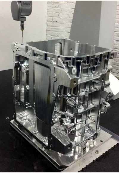
Brief introduction of milling process
Milling refers to the use of rotating multi-edge tools to mill workpieces, which is a highly efficient processing method. During milling, the tool rotates (for the main movement) and the workpiece moves (for the feed movement). The workpiece can also be fixed, but the rotating tool must also move (to complete the main movement and the feed movement at the same time). The machine tools used for milling are horizontal milling machines or vertical milling machines, as well as large portal milling machines. These machine tools can be ordinary machine tools or CNC milling machines. Use a rotating milling cutter as a cutting tool. Milling is generally performed on a milling machine or a boring machine, which is suitable for processing planes, grooves, various forming cavities (such as splines, gears and threads) and special curved surfaces of molds.The difference between turning and milling: Turning is used to machine parts of a rotating body. First fix the part on the three-jaw chuck and rotate it at high speed, and then use the turning tool to move the tool according to the generatrix of the revolving body to turn the product shape. The lathe can also process inner holes, threads, knurling, etc. The latter two are processed at low speed.
CNC milling processing technology
(1) Curve contours on the workpiece, straight lines, arcs, threads or spiral curves, especially curved surfaces such as non-circular curves and list curves given by mathematical expressions.(2) The spatial curve or surface of the mathematical model has been given.
(3) Although the shape is simple, the parts with many dimensions and difficult to detect.
(4) The inside of the cavity that is difficult to observe, control and detect when processed by ordinary machine tools.
(5) Holes or planes with strict size requirements.
(6) A simple surface or shape that can be processed by one-time clamping.
(7) General processing content that can effectively improve productivity and reduce labor intensity by using CNC milling processing.
The main processing objects suitable for CNC milling include the following categories: plane contour parts, variable bevel parts, spatial surface contour parts, holes and threads, etc.
① The teeth of the milling cutter periodically participate in intermittent cutting.
② The cutting thickness of each milling cutter tooth changes during the cutting process.
③ The feed per tooth αf (mm/tooth) indicates the relative displacement of the workpiece within the time that the milling cutter rotates one tooth.
Milled workpiece
(1) Flat parts (cavities, transmission boxes, bearing seats, gasoline and diesel case bodies, hydraulic and pneumatic valve bodies, rotary cylinders and oil cylinders, etc.)The characteristics of plane parts are shown in that the machined surface can be parallel to the horizontal plane, perpendicular to the horizontal plane, or at a fixed angle with the horizontal plane;
Most of the parts processed on the CNC milling machine belong to the plane part, and the plane part is the simplest type of parts in the CNC milling process. The two-axis linkage or three-axis linkage of a general 3-axis CNC milling machine can process plane parts. During the machining process, the machining surface is in surface contact with the tool, and end milling cutters or bull nose milling cutters can be used for rough and finishing.
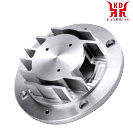
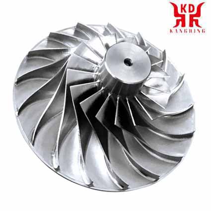
(2) Curved parts (impellers, marine propellers, diesel engine crankshafts, wind guide wheels, cams)
The characteristic of curved parts is that the machined surface is a space curved surface. During the machining process, the machined surface and the milling cutter are always in point contact. The surface finishing is mostly carried out with a ball-end milling cutter.
Milling parameters-definition
Cutting speed, vcRefers to the instantaneous speed of the cutting edge relative to the surface of the workpiece.
Effective or true cutting speed, ve
Refers to the instantaneous speed of the cutting edge at the effective diameter (DCap) relative to the surface to be machined. This value is a necessary condition for determining the actual cutting parameters corresponding to the actual cutting depth (ap). This is a particularly important value when using round insert milling cutters, ball-end end mills, all milling cutters with larger nose fillet radii, and milling cutters with an entering angle of less than 90°.
Spindle speed, n
The number of revolutions per minute of the milling cutter on the spindle. This is a machine-oriented value, which is calculated from the recommended cutting speed value of the process.
Feed per tooth, fz
A value used to calculate the table feed. The feed value per tooth is calculated from the recommended maximum chip thickness value.
Feed per revolution, fn
Indicates the movement distance of the tool during one revolution. It is specifically used to calculate the feed, and is usually used to determine the finishing capability of a milling cutter.
Feed per minute, vf
Also called table feed, machine tool feed or feed speed. It is the feed distance of the tool relative to the workpiece per unit time, and is related to the feed per tooth and the number of teeth of the milling cutter. The number of teeth (zn) available for milling cutters varies greatly; The effective number of teeth (zc) is the number of effective teeth involved in cutting, which is used to determine the table feed. The feed per revolution (fn) is a value specially used to calculate the feed. The unit is mm/r (inch/revolution). It is usually used to determine the finishing capacity of the milling cutter.
Maximum chip thickness, hex
This value describes the chip generated by the milling cutter and is related to fz, ae and kr. In order to ensure that the most productive table feed is used, chip thickness is an important consideration when determining the feed per tooth.
Average chip thickness, hm
The parameters describing the chips, together with the unit cutting force of the material being processed, are used to calculate the net power.
Metal removal rate, Q (cm3/min)
The amount of metal removed per minute, in mm3/min (cubic inches per minute). This value is determined by the depth of cut, width of cut and feed value.
Unit cutting force, kct
A material constant, which is also a coefficient used to calculate power, in N/mm2
Processing time, Tc (minutes)
It can be obtained by dividing the machining length (lm) by the table feed (vf).
Net power Pc and efficiency ηmt
The machine-oriented value is used to help calculate the net power required to ensure that the machine is suitable for the relevant milling cutter and process.
Milling technology-definition
Linear ramp millingA linear motion that is carried out simultaneously along the axial and radial feed directions of the milling cutter.
Arc milling
Contour arc milling tool path (circular interpolation).
Helical interpolation milling
Circular ramping milling tool path (helical interpolation).
Contour milling
Contour milling.
Point milling
Short radial contact cutting where the cutting area performed with a round insert or a ball-end milling cutter is far from the center of the tool.
Milling fan-shaped bumps
A sharp point that appears when processing complex curved surfaces.


