DMG Five-axis Milling and Turning Complex Machining Ultra-thin Outer Casing
Key words: milling and turning composite machining, ultra-thin casing machining, milling and turning composite machining tools, milling and vehicle composite machining fixture design
Selection of milling and turning composite processing equipment
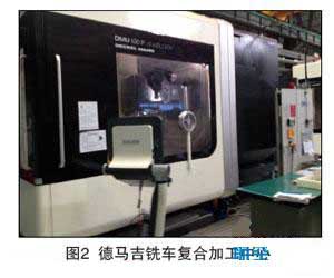
The ultra-thin shell processing equipment is selected from the Demag five-coordinate milling and turning machining center (as shown in Figure 2). The machine uses an electric spindle head with a 45° angle and is driven by a linear motor. The servo drive system has high precision, good reliability and fast response. There is enough static and dynamic stiffness to ensure the system has good dynamic quality and thermal stability. The device should have high precision, high reliability, and an Ethernet interface to network with computers and other devices. It realizes the transmission of CNC machining program, various process parameters and machine state information, and can adapt to the processing of difficult-to-machine materials such as high-temperature alloys and titanium alloys. It can complete milling, turning, drilling, expanding, reaming, boring, etc. in one setup, and can be used for precision positioning holes on aerospace parts and semi-finishing and finishing of outer surfaces. The machine is powerfully milled and equipped with SHOPMILL milling software. The workbench can realize dynamic balance and analyze the balance action point to assist the turning function. With online detection function, it can realize online simulation of car and milling. The main technical parameters of the machine are as follows:
Axis stroke: ≥1250mm;
Y-axis travel: ≥1000mm;
Z-axis travel: ≥1000mm;
Workbench size: ≥ φ1250mm;
Maximum turning diameter: ≥ φ1400mm;
Workbench load: ≥2000kg.
C axis (workbench) rotation range: ≥ ± 360 °, positioning accuracy: ≤ 7′′, repeat positioning accuracy: ≤ 4′′.
Worktable milling maximum speed: ≥20r/min,
Maximum turning speed: ≥500r/min,
Maximum turning torque (S1): ≥ 5400 N•m,
Maximum power for turning (S1): ≥35kW.
 2. Fixture design for milling process
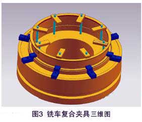
The milling and turning combined machining technology needs to realize the processing of most of the dimensions in one clamping, and the tooling fixture is crucial to play. Otherwise, it has to be clamped many times, which will inevitably reduce the processing efficiency. The technology of milling and turning composite machining technology is that the inner surface is generally turned by turning, the outer surface includes turning and boring and milling, and the end face or radial hole is processed by drilling, boring and reaming. Therefore, the milling and turning combined machining needs to design a fixture that can be positioned and clamped inside and outside, and can be quickly disassembled. The ultra-thin shell milling and turning combined machining fixture adopts internal and external pressure plate structure (as shown in Figure 3). Through the way of backpressure plate, the internal and external profiles can be processed by one-time clamping, turning and milling.
3. Selection of Tools for Milling-Turning Compound Machining
The DMG five-axis milling and turning machining center is equipped with 40 ATC tool magazines. The spindle taper hole size is HSK-A100. In order to give full play to the automatic tool changing function of the machining center, the clamping tool with Iska modular structure is used in the machining of the outer casing (as shown in Figure 4). Combined with the rotation function of the spindle head of the DMG five-coordinate milling and turning machining center, the azimuth attitude of the turning tool is changed. A tool is used to machine different positions on the inner and outer surfaces, saving the number of tools and reducing tool costs.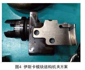
4. Programming of Milling Turning Compound Processing
According to the characteristics of CNC programming of milling and turning machining center, it is divided into two modes: milling and machining. The milling mode is DM_MILL and the machining mode is DM_TURN. In the preparation of the five-axis linkage milling program, it is necessary to activate the 5-axis machining tool nose tracking function, the CNC machining path forward-looking function G64 and the machining axis synchronization coordination function FGROUP. In the preparation of the CNC machining program, the balance function of the Demag five-axis machining center is required. The counterweight position indicated on the machine screen, the counterweight blocks of the same weight are allocated according to the weight prompted by the system to ensure the balance of the turning system.
In the process of compiling milling program, the post-processing of milling-turning compound processing is developed by Siemens subsystem. Application of Siemens 840D language instructions and machine-specific features. For example, TRAORI (1), CYCLE800, CYCLE81-CYCLE86, polar coordinates. The machine tool, milling, drilling, boring, tapping and other methods are integrated into one machine. The combined processing technology of milling and turning realizes the combined processing of multiple processes of turning, milling, drilling and boring. In the Turning-Milling process, it is necessary to remove the uneven parts of the allowance under the condition that the overall rigidity is sufficient, so that the milling and turning allowances are consistent. According to the structure and rigidity of the part, choose milling to ensure the wall thickness or the machining to ensure the wall thickness; After all dimensions are machined, the technical conditions of the datum are measured and the datum is repaired. After all turning and milling processes are completed, drilling, boring and tapping are carried out.
For this part, the route of arranging NC process is as follows:
Rough milling profile (leaving 0.3mm margin)- Rough turning inner and outer surfaces (leaving 0.3mm margin)- Fine turning of inner and outer surfaces (with 0.1mm margin at datum level)- Finish milling- Precision turning datum- Drilling and Boring Radial Holes and Milling Threads- Drilling and boring end faces.
5. On-line measurement of milling and compounding process
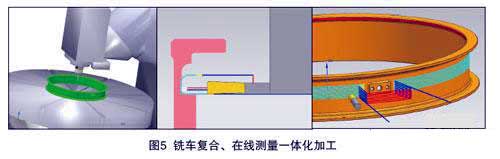
The DMG five-axis milling and turning machining center is equipped with Renishaw probes and infrared receivers with on-line measurement. In the ultra-thin shell car composite processing, the online measurement function is applied. Using the Renishaw probe to complete the automatic alignment of the parts, the machining coordinate system is automatically set, and the integrated measurement of on-line measurement and milling is realized (as shown in Fig. 5). The automatic alignment procedure for on-line measurement of housing is as follows:
CYCLE800
TRAFOOF
DM_MILL
T999
M6... ;______ Single point measurement Z-axis zero position, set coordinate frame G54 _______
_TUL=1_TLL=-1
_PRNUM=1_NMSP=1_VMS=0
_TSA=20_FA=15_KNUM=1
_MVAR=100_MA=3
_SETVAL=0
CYCLE978
G54 ;____ Single point measurement Z-axis zero position, set coordinate frame G54 _________G0X0Y0Z-2; ____ single point measurement X, Y axis zero position, set coordinate frame G54 _________ _TUL=1_TLL=-1
_PRNUM=1_NMSP=1_VMS=0
_TSA=20_FA=15_KNUM=1
_MVAR=101_MA=3
_SETVAL=433_STA1=0
_INCA=90_CPA=0_CPO=0
_KNUM=1
CYCLE979
G54; ____ single point measurement X, Y axis zero position, set coordinate frame G54 _________M28
G0Z500
M02
6. Simulation and verification of milling and rolling compound program
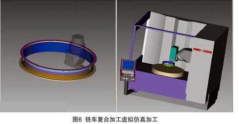
VERICUT is a powerful machining simulation software that analyzes CNC programs through simulation. It can be found whether there are overcutting, residual and other phenomena in the processing, to prevent interference and collision, and to verify the correctness and rationality of the NC machining program. Especially in the process of developing new parts, it can verify the correctness of the program through machining simulation. This can save expensive test piece costs, save unnecessary processing time, and play a very important role in the development of new parts. In order to verify the accuracy of the milling program, the simulation environment of the DMU125FD milling five-axis machining center was built by VERICUT7.0 software. The virtual simulation processing verification of the ultra-thin shell car composite machining program is completed, which ensures the correctness of the program. The simulation machine tool structure is shown in Fig. 6.
Result analysis
Problems existing in routine methods and routes:
(1) The process of turning, milling, drilling and boring is too scattered, the waiting time for production preparation time and turnover between processes is long, and it takes up more processing equipment, which affects the processing efficiency and delivery schedule;
(2) The actual values of some dimensions are close to the theoretical limit values. If not controlled, the partial dimensions may be out of tolerance;
(3) The NC program and processing parameters need to be optimized and refined;
(4) Tool consumption is too large.
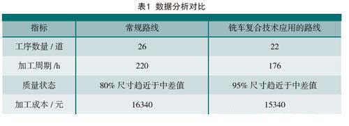
Through the processing of test pieces and real parts on site, according to the application of lean engineering concept. The benefits of the new technology and methods are analyzed by the number of processes, processing cycle, quality status and processing cost. The data analysis and comparison are shown in Table 1.
Through comparative analysis of experimental data. It is verified that the milling and turning composite processing technology is beneficial to improve the processing efficiency of the aircraft engine casing, save the fixture and reduce the processing cost. Avoid the correction error of the secondary clamping caused by the deformation of the thin-walled casing, and ensure the processing quality of the thin-walled machine.
in conclusion
Through the application of milling and turning combined machining technology in the processing of aerospace thin-walled casings, the importance of the functions of the milling and turning complex machining center equipment is further recognized. Mastered the online measurement automatic alignment, milling and compounding automatic tool change processing, milling and vehicle composite virtual simulation processing and other processing technologies. The typical process route of the integrated processing of the overall annular thin-walled shell milling machine is formed. The milling and turning combined machining technology is used to improve the process and fully utilize the functions of the machine tool. The process route has been shortened, and processing techniques such as online measurement, turning and milling, and virtual simulation have been adopted. It ensures the reliability of the processing process, can greatly improve the processing efficiency, reduce the processing cost, and ensure the processing quality.
Selection of milling and turning composite processing equipment
The ultra-thin shell processing equipment is selected from the Demag five-coordinate milling and turning machining center (as shown in Figure 2). The machine uses an electric spindle head with a 45° angle and is driven by a linear motor. The servo drive system has high precision, good reliability and fast response. There is enough static and dynamic stiffness to ensure the system has good dynamic quality and thermal stability. The device should have high precision, high reliability, and an Ethernet interface to network with computers and other devices. It realizes the transmission of CNC machining program, various process parameters and machine state information, and can adapt to the processing of difficult-to-machine materials such as high-temperature alloys and titanium alloys. It can complete milling, turning, drilling, expanding, reaming, boring, etc. in one setup, and can be used for precision positioning holes on aerospace parts and semi-finishing and finishing of outer surfaces. The machine is powerfully milled and equipped with SHOPMILL milling software. The workbench can realize dynamic balance and analyze the balance action point to assist the turning function. With online detection function, it can realize online simulation of car and milling. The main technical parameters of the machine are as follows:
Axis stroke: ≥1250mm;
Y-axis travel: ≥1000mm;
Z-axis travel: ≥1000mm;
Workbench size: ≥ φ1250mm;
Maximum turning diameter: ≥ φ1400mm;
Workbench load: ≥2000kg.
C axis (workbench) rotation range: ≥ ± 360 °, positioning accuracy: ≤ 7′′, repeat positioning accuracy: ≤ 4′′.
Worktable milling maximum speed: ≥20r/min,
Maximum turning speed: ≥500r/min,
Maximum turning torque (S1): ≥ 5400 N•m,
Maximum power for turning (S1): ≥35kW.
The milling and turning combined machining technology needs to realize the processing of most of the dimensions in one clamping, and the tooling fixture is crucial to play. Otherwise, it has to be clamped many times, which will inevitably reduce the processing efficiency. The technology of milling and turning composite machining technology is that the inner surface is generally turned by turning, the outer surface includes turning and boring and milling, and the end face or radial hole is processed by drilling, boring and reaming. Therefore, the milling and turning combined machining needs to design a fixture that can be positioned and clamped inside and outside, and can be quickly disassembled. The ultra-thin shell milling and turning combined machining fixture adopts internal and external pressure plate structure (as shown in Figure 3). Through the way of backpressure plate, the internal and external profiles can be processed by one-time clamping, turning and milling.
3. Selection of Tools for Milling-Turning Compound Machining
The DMG five-axis milling and turning machining center is equipped with 40 ATC tool magazines. The spindle taper hole size is HSK-A100. In order to give full play to the automatic tool changing function of the machining center, the clamping tool with Iska modular structure is used in the machining of the outer casing (as shown in Figure 4). Combined with the rotation function of the spindle head of the DMG five-coordinate milling and turning machining center, the azimuth attitude of the turning tool is changed. A tool is used to machine different positions on the inner and outer surfaces, saving the number of tools and reducing tool costs.
4. Programming of Milling Turning Compound Processing
According to the characteristics of CNC programming of milling and turning machining center, it is divided into two modes: milling and machining. The milling mode is DM_MILL and the machining mode is DM_TURN. In the preparation of the five-axis linkage milling program, it is necessary to activate the 5-axis machining tool nose tracking function, the CNC machining path forward-looking function G64 and the machining axis synchronization coordination function FGROUP. In the preparation of the CNC machining program, the balance function of the Demag five-axis machining center is required. The counterweight position indicated on the machine screen, the counterweight blocks of the same weight are allocated according to the weight prompted by the system to ensure the balance of the turning system.
In the process of compiling milling program, the post-processing of milling-turning compound processing is developed by Siemens subsystem. Application of Siemens 840D language instructions and machine-specific features. For example, TRAORI (1), CYCLE800, CYCLE81-CYCLE86, polar coordinates. The machine tool, milling, drilling, boring, tapping and other methods are integrated into one machine. The combined processing technology of milling and turning realizes the combined processing of multiple processes of turning, milling, drilling and boring. In the Turning-Milling process, it is necessary to remove the uneven parts of the allowance under the condition that the overall rigidity is sufficient, so that the milling and turning allowances are consistent. According to the structure and rigidity of the part, choose milling to ensure the wall thickness or the machining to ensure the wall thickness; After all dimensions are machined, the technical conditions of the datum are measured and the datum is repaired. After all turning and milling processes are completed, drilling, boring and tapping are carried out.
For this part, the route of arranging NC process is as follows:
Rough milling profile (leaving 0.3mm margin)- Rough turning inner and outer surfaces (leaving 0.3mm margin)- Fine turning of inner and outer surfaces (with 0.1mm margin at datum level)- Finish milling- Precision turning datum- Drilling and Boring Radial Holes and Milling Threads- Drilling and boring end faces.
5. On-line measurement of milling and compounding process
The DMG five-axis milling and turning machining center is equipped with Renishaw probes and infrared receivers with on-line measurement. In the ultra-thin shell car composite processing, the online measurement function is applied. Using the Renishaw probe to complete the automatic alignment of the parts, the machining coordinate system is automatically set, and the integrated measurement of on-line measurement and milling is realized (as shown in Fig. 5). The automatic alignment procedure for on-line measurement of housing is as follows:
CYCLE800
TRAFOOF
DM_MILL
T999
M6... ;______ Single point measurement Z-axis zero position, set coordinate frame G54 _______
_TUL=1_TLL=-1
_PRNUM=1_NMSP=1_VMS=0
_TSA=20_FA=15_KNUM=1
_MVAR=100_MA=3
_SETVAL=0
CYCLE978
G54 ;____ Single point measurement Z-axis zero position, set coordinate frame G54 _________G0X0Y0Z-2; ____ single point measurement X, Y axis zero position, set coordinate frame G54 _________ _TUL=1_TLL=-1
_PRNUM=1_NMSP=1_VMS=0
_TSA=20_FA=15_KNUM=1
_MVAR=101_MA=3
_SETVAL=433_STA1=0
_INCA=90_CPA=0_CPO=0
_KNUM=1
CYCLE979
G54; ____ single point measurement X, Y axis zero position, set coordinate frame G54 _________M28
G0Z500
M02
6. Simulation and verification of milling and rolling compound program
VERICUT is a powerful machining simulation software that analyzes CNC programs through simulation. It can be found whether there are overcutting, residual and other phenomena in the processing, to prevent interference and collision, and to verify the correctness and rationality of the NC machining program. Especially in the process of developing new parts, it can verify the correctness of the program through machining simulation. This can save expensive test piece costs, save unnecessary processing time, and play a very important role in the development of new parts. In order to verify the accuracy of the milling program, the simulation environment of the DMU125FD milling five-axis machining center was built by VERICUT7.0 software. The virtual simulation processing verification of the ultra-thin shell car composite machining program is completed, which ensures the correctness of the program. The simulation machine tool structure is shown in Fig. 6.
Result analysis
Problems existing in routine methods and routes:
(1) The process of turning, milling, drilling and boring is too scattered, the waiting time for production preparation time and turnover between processes is long, and it takes up more processing equipment, which affects the processing efficiency and delivery schedule;
(2) The actual values of some dimensions are close to the theoretical limit values. If not controlled, the partial dimensions may be out of tolerance;
(3) The NC program and processing parameters need to be optimized and refined;
(4) Tool consumption is too large.
Through the processing of test pieces and real parts on site, according to the application of lean engineering concept. The benefits of the new technology and methods are analyzed by the number of processes, processing cycle, quality status and processing cost. The data analysis and comparison are shown in Table 1.
Through comparative analysis of experimental data. It is verified that the milling and turning composite processing technology is beneficial to improve the processing efficiency of the aircraft engine casing, save the fixture and reduce the processing cost. Avoid the correction error of the secondary clamping caused by the deformation of the thin-walled casing, and ensure the processing quality of the thin-walled machine.
in conclusion
Through the application of milling and turning combined machining technology in the processing of aerospace thin-walled casings, the importance of the functions of the milling and turning complex machining center equipment is further recognized. Mastered the online measurement automatic alignment, milling and compounding automatic tool change processing, milling and vehicle composite virtual simulation processing and other processing technologies. The typical process route of the integrated processing of the overall annular thin-walled shell milling machine is formed. The milling and turning combined machining technology is used to improve the process and fully utilize the functions of the machine tool. The process route has been shortened, and processing techniques such as online measurement, turning and milling, and virtual simulation have been adopted. It ensures the reliability of the processing process, can greatly improve the processing efficiency, reduce the processing cost, and ensure the processing quality.


