Parts Processing Mapping Software
1.1 Introduction to Auto CAD Drafting Software
The most widely used computer graphics software, Auto CAD, is a general-purpose computer-aided drawing and design software developed by Autodesk of the United States.
Auto CAD is mainly equipped with features such as powerful, easy to grasp, easy to use, open architecture, etc. It is capable of drawing plane graphics and 3D graphics, dimensioning graphics, rendering graphics, and printout drawings. By the majority of engineering and technical personnel welcome.
(a) drawing and editing planes and three-dimensional graphics
Users can use the rich drawing commands provided by Auto CAD2010 to draw straight lines, construction lines, polylines, circles, rectangles, polygons, ellipses, and other basic graphics, and can also draw a variety of two-dimensional graphics.
At the same time, it can be easily converted to a three-dimensional graphic by stretching, setting elevation, and thickness. In the axis side mode of Auto CAD 2010, the user can easily draw an axis side view.
(b) Dimensioning graphics
Labeling the dimensions of the graphic is an indispensable step in the entire drawing process. Users can use Auto CAD2010 to quickly and easily create various types of annotations in all directions of two-dimensional or three-dimensional graphics. Auto CAD2010 provides users with three basic types of annotations: linearity, radius, and angle. Users can make horizontal, vertical, alignment, rotation, coordinates, baseline, or continuous labels. In addition, users can also rotate lead labels, tolerance labels, and custom roughness labels.
(c) rendering three-dimensional graphics
Users can use the atomization, light source, and material to render the model to increase its realism. Users can perform full or partial rendering according to actual needs for the best results.
(d) Printout drawings
Auto CAD2010 supports printout graphics and supports importing graphics in different formats into Auto CAD2010 or exporting graphics drawn in Auto CAD2010 into other formats for use in other programs.
The above is the basic function of Auto CAD2010, which shows that its function is really powerful. This also makes it widely used in various fields
1.2. Introduction to SolidWork Mapping Software
SolidWorks software is the world's first three-dimensional CAD system based on Windows development, technological innovation in line with the development trend and trend of CAD technology
(1) Features of solidworks software
Solidworks software is powerful and has many components. Solidworks' powerful, easy-to-learn and easy-to-use technology innovations are the three major features of SolidWorks, making SolidWorks a leading, mainstream 3D CAD solution. SolidWorks can provide different design solutions, reduce errors in the design process, and improve product quality. SolidWorks not only provides such a powerful feature, but also makes it easy for each engineer and designer to operate and learn.
For users familiar with Microsoft's Windows system, you can basically use SolidWorks to design. SolidWorks' unique drag-and-drop features allow users to complete large-scale assembly designs in a relatively short period of time. SolidWorks Explorer is the same CAD file manager as Windows Explorer. It can be used to easily manage CAD files. With SolidWorks, users can complete more work in a relatively short period of time, and can quickly put high-quality products on the market.
Among the three-dimensional CAD solutions that are currently on the market, SolidWorks is one of the simpler and more convenient design software.
The famous American consulting company Daratech commented: "In the Windows platform-based three-dimensional CAD software, SolidWorks is the most famous brand, is the market leader in rapid growth."
In collaboration with powerful design features and easy-to-learn and easy-to-use operations (including Windows-style drag/drop, click/click, cut/paste), With SolidWorks, the entire product design is 100% editable, parst design, assembly design and engineering drawing are all related.
(2) solidworks drawing steps
1, shaft parts (see Figure P4-1, Figure 4-1-1)
(1) Enter the drawing interface, Front plane enters select sketching, drawing sketches in FIG.
(2) exit the sketch, wherein the rotary projections, as shown in FIG.
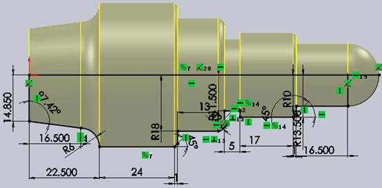
(3) Draw the left end hole in Figure 1:
1) Enter features, special hole guide, select straight hole, diameter is 20mm, depth is 30mm, Make sure that the center of the circle coincides with the diameter of 29.7mm and the center of the circle;
2) Draw a sketch based on the left end face. The center of the circle is the origin of the coordinate. The diameter is 24mm. Exit the sketch.
Extruded and cut to a depth of 22.5mm.
3) Draw the chamfer at the leftmost C1.5.
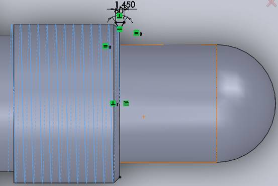
(4) Drawing M30 × 1.5 male thread:
1) Draw a helix with a circle of 27 mm diameter and set a pitch of 1.5 and a depth of 21 mm. Exit the sketch.
2) Sketch the above reference plane as shown in the figure. Exit the sketch, select the feature and remove it, the path is set as a spiral. Complete the thread drawing.
(5) Save the entity and exit the drawing interface.
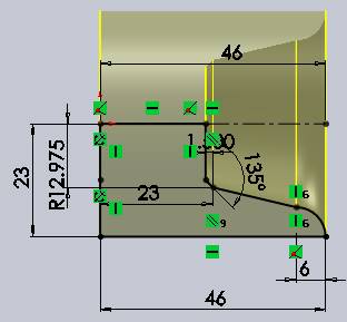
2, Sleeve Parts
(1) Enter the drawing interface, select the front view plane to enter the sketch, draw a sketch as shown.
(2) Exit sketches, features, and rotation bosses as shown.
(3) Draw the left M27 × 1.5-6H internal thread.
Entering Hole Wizard, the hole type: straight thread hole; standard: GB;
Size: M27; Depth: 30 mm; hole position coincides with the dot. Make sure that the internal thread hole is completed.
(4) Save the entity and exit the drawing interface
The most widely used computer graphics software, Auto CAD, is a general-purpose computer-aided drawing and design software developed by Autodesk of the United States.
Auto CAD is mainly equipped with features such as powerful, easy to grasp, easy to use, open architecture, etc. It is capable of drawing plane graphics and 3D graphics, dimensioning graphics, rendering graphics, and printout drawings. By the majority of engineering and technical personnel welcome.
(a) drawing and editing planes and three-dimensional graphics
Users can use the rich drawing commands provided by Auto CAD2010 to draw straight lines, construction lines, polylines, circles, rectangles, polygons, ellipses, and other basic graphics, and can also draw a variety of two-dimensional graphics.
At the same time, it can be easily converted to a three-dimensional graphic by stretching, setting elevation, and thickness. In the axis side mode of Auto CAD 2010, the user can easily draw an axis side view.
(b) Dimensioning graphics
Labeling the dimensions of the graphic is an indispensable step in the entire drawing process. Users can use Auto CAD2010 to quickly and easily create various types of annotations in all directions of two-dimensional or three-dimensional graphics. Auto CAD2010 provides users with three basic types of annotations: linearity, radius, and angle. Users can make horizontal, vertical, alignment, rotation, coordinates, baseline, or continuous labels. In addition, users can also rotate lead labels, tolerance labels, and custom roughness labels.
(c) rendering three-dimensional graphics
Users can use the atomization, light source, and material to render the model to increase its realism. Users can perform full or partial rendering according to actual needs for the best results.
(d) Printout drawings
Auto CAD2010 supports printout graphics and supports importing graphics in different formats into Auto CAD2010 or exporting graphics drawn in Auto CAD2010 into other formats for use in other programs.
The above is the basic function of Auto CAD2010, which shows that its function is really powerful. This also makes it widely used in various fields
1.2. Introduction to SolidWork Mapping Software
SolidWorks software is the world's first three-dimensional CAD system based on Windows development, technological innovation in line with the development trend and trend of CAD technology
(1) Features of solidworks software
Solidworks software is powerful and has many components. Solidworks' powerful, easy-to-learn and easy-to-use technology innovations are the three major features of SolidWorks, making SolidWorks a leading, mainstream 3D CAD solution. SolidWorks can provide different design solutions, reduce errors in the design process, and improve product quality. SolidWorks not only provides such a powerful feature, but also makes it easy for each engineer and designer to operate and learn.
For users familiar with Microsoft's Windows system, you can basically use SolidWorks to design. SolidWorks' unique drag-and-drop features allow users to complete large-scale assembly designs in a relatively short period of time. SolidWorks Explorer is the same CAD file manager as Windows Explorer. It can be used to easily manage CAD files. With SolidWorks, users can complete more work in a relatively short period of time, and can quickly put high-quality products on the market.
Among the three-dimensional CAD solutions that are currently on the market, SolidWorks is one of the simpler and more convenient design software.
The famous American consulting company Daratech commented: "In the Windows platform-based three-dimensional CAD software, SolidWorks is the most famous brand, is the market leader in rapid growth."
In collaboration with powerful design features and easy-to-learn and easy-to-use operations (including Windows-style drag/drop, click/click, cut/paste), With SolidWorks, the entire product design is 100% editable, parst design, assembly design and engineering drawing are all related.
(2) solidworks drawing steps
1, shaft parts (see Figure P4-1, Figure 4-1-1)
(1) Enter the drawing interface, Front plane enters select sketching, drawing sketches in FIG.
(2) exit the sketch, wherein the rotary projections, as shown in FIG.
(3) Draw the left end hole in Figure 1:
1) Enter features, special hole guide, select straight hole, diameter is 20mm, depth is 30mm, Make sure that the center of the circle coincides with the diameter of 29.7mm and the center of the circle;
2) Draw a sketch based on the left end face. The center of the circle is the origin of the coordinate. The diameter is 24mm. Exit the sketch.
Extruded and cut to a depth of 22.5mm.
3) Draw the chamfer at the leftmost C1.5.
(4) Drawing M30 × 1.5 male thread:
1) Draw a helix with a circle of 27 mm diameter and set a pitch of 1.5 and a depth of 21 mm. Exit the sketch.
2) Sketch the above reference plane as shown in the figure. Exit the sketch, select the feature and remove it, the path is set as a spiral. Complete the thread drawing.
(5) Save the entity and exit the drawing interface.
2, Sleeve Parts
(1) Enter the drawing interface, select the front view plane to enter the sketch, draw a sketch as shown.
(2) Exit sketches, features, and rotation bosses as shown.
(3) Draw the left M27 × 1.5-6H internal thread.
Entering Hole Wizard, the hole type: straight thread hole; standard: GB;
Size: M27; Depth: 30 mm; hole position coincides with the dot. Make sure that the internal thread hole is completed.
(4) Save the entity and exit the drawing interface


