GM Sleeve Part Manufacturing Process Analysis
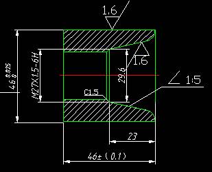
The workpiece length is 46mm; the outer circle size is 64mm, and the roughness requirement is Ra1.6, which requires finishing;
Inner hole: The left end is a length of 23 mm (including C1.5 chamfer),
Nominal diameter 27 mm, pitch 1.5, tolerance class 6H ordinary threads; the right end is a tapered hole with a slope of 1:5. the rounded corners of R6, the taper roughness is Ra1.6 and requires finishing.
(A) analysis of the sleeve part
The figure shows a simple sleeve part, in which a plurality of diameter dimensions and axial dimensions have higher dimensional accuracy and surface roughness requirements, and the dimension of the part is marked in a complete manner, which meets the requirements for the dimensioning of the NC machining;
The contour description is clear and complete; the material of the part is No. 45 steel, and the machining and cutting performance is good. The heat treatment: modulation treatment, HRC25-35 has no hardness requirements.
Sleeve part is machined common form of processing, In addition to the size and shape accuracy of the sleeve part, the inner hole is generally used as a reference for assembly. the hole diameter tolerance grade is generally IT7, the precision bushing may take IT6, and the hole shape accuracy shall be controlled within the aperture tolerance.
For longer-length bushing parts, in addition to the roundness requirements, attention should be paid to the cylindricity of the inner hole face, the round runout and verticality of the inner hole axis of the end face, and the parallelism of both end faces.
(B) Sleeve part's clamping solution
Sleeve part inside and outside the circle, the end surface and the reference axis have a certain degree of accuracy requirements, the outline part of the fine reference can choose the outer circle, but often with the center line and an end face for the finishing reference. For different parts of the structure, it is not possible to use a process scheme to ensure its accuracy requirements.
According to the structural features of the sleeve part, three-jaw chucks, four-jaw chucks, or face plate clamping can be used in CNC machining. Due to the error in centering accuracy of the jaw chucks, it is not suitable for secondary clamping of workpieces with high coaxiality requirements. For three-jaw chucking, the sleeve part can be processed once to complete the inner and outer circle end faces, chamfering, and cutting. Larger parts often use four-claw or disk clamping; For soft parts, soft jaw clamping can be used. Clamping can also be used on the spindle; For a more complex sleeve part, special fixtures are sometimes used for clamping.
(c) Selection of tools
cylindrical outer sleeve part machining tool,Same as shaft parts. Processing inner hole is one of the features of the sleeve part. According to the inner hole process requirements, there are many processing methods, such as drilling, reaming, boring, grinding, drawing holes, and grinding holes.
sleeve part generally includes internal and external circles, cones, arcs, slots, holes, threads and other structures.According to the processing requirements, the commonly used tools include roughing bo ring tools, fine boring tools, internal boring tools, internal thread turning tools, and special-shaped turning tools.
(D) Selection of cutting amount
According to the surface quality requirements, tool material and workpiece material, Refer to the cutting amount manual or related data to select the cutting speed and feedrate per revolution, then calculate the spindle speed and feedrate (the calculation process is omitted), and fill the results into the process card.
The choice of cutting depth varies depending on the rough and finish machining. During roughing, if the rigidity of the process system and the power of the machine allow, take as large a depth of cut as possible to reduce the number of feeds; During finish machining, in order to ensure the surface roughness of the parts, the cutting depth is generally 0.1-0.4mm.
(E) Selection of cutting fluid
Sleeve part has greater difficulty in CNC machining than shaft parts. Due to the features of the sleeve part, the cutting fluid is not easy to reach the cutting area, the cutting area temperature is high, and the wear of the cutting tool is relatively serious. In order to reduce the processing distortion of the workpiece and improve the machining accuracy, a suitable cutting fluid pouring position should be selected according to different workpiece materials.
(F) Fill in processing tools and operation cards
(1) According to the processing sequence, the processing contents of each step, the used tool and the amount of cuttings, etc., are filled into the CNC machining process card.
(2) Insert the tool type, insert type, blade number, and tip radius of the selected tool for each step into the CNC tooling card.
(3) Drawing the route of each work step into a file path plan.
CNC tool card
|
Product name and code |
Examples of CNC turning technology |
Part Name |
Cone sleeve nut |
Part number |
|
Program number |
|
||||||||||||
|
Step number |
Tool number |
Tool specification and name (mm) |
Quantity |
Machining surface |
Tool nose radius (mm) |
Note |
|||||||||||||
|
1 |
T01 |
45° external turning tool1 |
Turning end face and cylindrical surface |
0.5 |
|
||||||||||||||
|
2 |
T02 |
Ø4 center drill |
1 |
Drill Ø4 center hole |
|
|
|||||||||||||
|
3 |
T03 |
Ø 23.5 twist drill |
1 |
drilling |
|
|
|||||||||||||
|
4 |
T04 |
Hole boring tool |
1 |
Rough bore and Inner conical face |
0.4 |
|
|||||||||||||
|
5 |
T05 |
Hole boring tool |
1 |
Fine bore and Inner conical face |
0.2 |
|
|||||||||||||
|
6 |
T06 |
Internal thread turning tool |
1 |
Turning internal thread and thread hole chamfer |
0.3 |
|
|||||||||||||
|
prepared by |
Liu Xin |
Review |
|
Approved |
|
Total one page |
First page |
||||||||||||
CNC machining process card
| Kangding metal |
CNC machining process card |
Product name or code |
set |
Materials |
Part number |
||||||||||||||
|
Examples of CNC turning technology |
Cone nut set |
45 # steel |
|
||||||||||||||||
|
employee ID |
Program number |
Fixture number |
use equipment |
|
Workshop |
||||||||||||||
|
|
O0010 |
|
CK6140 |
|
CNC Center |
||||||||||||||
|
Step number |
Step content |
Tool number |
Tool specifications (mm) |
Spindle speed (r/min) |
Feed rate f/(mm/r) |
Depth of cut ap/mm |
Note |
||||||||||||
|
1 |
Flat end surface |
T01 |
25×25 |
350 |
|
1 |
Manually
|
||||||||||||
|
2 |
Drilling center hole |
T02 |
Ø4 |
800 |
|
2 |
Manually |
||||||||||||
|
3 |
drilling |
T03 |
Ø 20 |
200 |
|
15 |
Manually | ||||||||||||
|
4 |
Heavy boring hole circle (inverted) angle and slope |
T04 |
20×20 |
500 |
40 |
0.8 |
automatic |
||||||||||||
|
5 |
Right boring inner hole fillet and bevel, guaranteed slope (1:5), Ra6 |
T05 |
20×20 |
800 |
40 |
0.2 |
automatic |
||||||||||||
|
6 |
rough turning outer surface to size |
T01 |
25×25 |
500 |
40 |
1.5 |
automatic |
||||||||||||
|
7 |
Turn the other side of the car to ensure the length dimension |
T01 |
25×25 |
500 |
|
|
Manually |
||||||||||||
|
8 |
rough turning inner thread |
T06 |
16×16 |
500 |
|
0.4 |
automatic |
||||||||||||
|
9 |
finish turning inner thread |
T06 |
16×16 |
800 |
|
0.1 |
automatic |
||||||||||||
|
10 |
finish turning outer surface |
T01 |
25×25 |
1000 |
|
|
Manually |
||||||||||||
|
prepared by |
Liu Xin |
Review |
|
Approved |
|
Total one page |
First page |
||||||||||||
Table 4-4
(g) sleeve part processing programmingO0010 program number
N001 G21 G99 G97 G40; Initialization procedure
N002 M03 S500 T0404; Spindle rotation, speed 500, No. 4 knife and tool compensation
N003 G00 X23 Z2; Rapid positioning cycle start (23,2)
N004 G71 U1.0 R0.5; Rough bore
N005 G71 P006 Q014 U-0.3 W0.1 F0.15; Rough boring, X direction margin 0.3mm, Z direction margin 0.1 mm
N006 G00 X46 Z2; Approaching surface to be machined
N007 G01 Z0; Approaching surface to be machined
N008 G02 X34 Z-6 R6; Turn counterclockwise to (34,-6), Radius: R6
N09 G01 X29.6 Z-23; Straight path to point (29.6, -23)
N010 X26.55; Straight line to point (26.55, -23)
N011 X25.05 Z-24.5; Straight path to point (25.05,-24.5)
N012 Z-46; Straight line to point (25.05, -46)
N013 X0; Retract to point (0, -46)
N014 G00 Z50; Quick retract to Z50
N015 X100; Retract to tool change point
N016 M05; Spindle stalled
N017 G21 G97 G99 G40; Initialization procedure
N018 M03 S800 T0505; Spindle forward rotation, speed 800, tool No. 5 and tool compensation
N019 G00 X23 Z2; rapid positioning cycle start (23,2)
N020 G70 P006 Q014 F0.15; Fine bore
N021 G00 X100; Retract to tool change point
N022 M05; Spindle stop
N023 G21 G97 G99 G40; Initialization procedure
N024 M03 S500 T0101; Spindle rotation, speed 500, change No. 1 knife and tool compensation
N025 G00 X48Z2; Quick Positioning
N026 G01 Z-32; Straight line to point (48,-32)
N027 U2 Straight to point (50, -32)
N028 G00 Z2; Quick Positioning to Point (50,2)
N029 G01 X46.5; Straight path to point (46.5,2)
N030 Z-32; Straight pass to point (46.5, -32)
N031 U4; Straight line to point (50,-32)
N032 G00 Z2; Quick Positioning to Point (50,2)
N033 X100,Z50; Quick positioning to tool change point
N034 MO3; Spindle stalled
N035 M05; Program stopped
O0011 program number (Turn inner thread)
N001 G21 G99 G97 G40; Initialization procedure
N002 M03 S500 T0101; Spindle rotation, speed 500, No. 1 knife and tool compensation
N003 G00 X48Z2; Quick positioning
N004 G01 Z-32; Straight pass to point (48,-32)
N026 M05; Program stopped


