Shaft Parts Process Plan Analysis
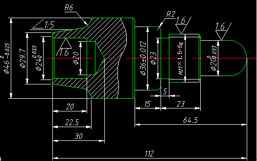
Figure 1-1
(2) Analysis of Parts Drawings
The surface of the part is composed of a cylinder, a straight arc, an inverse arc, a cone, a groove, a thread, a hole, and the like. The dimensioning is complete. The blank is 45# steel Φ50mm×120mm. Heat treatment: Modulation treatment, HRC25-35 has no hardness requirement.
(3) Determine the processing method:
The principle of selection of the processing method is to ensure the processing accuracy and surface roughness of the machined surface.
Because there are many processing methods for obtaining the same level of precision and surface roughness, comprehensive considerations such as the shape, size, and tolerance requirements of the shape and position of the parts must be taken into account in the actual selection. In the figure, several precisions require higher dimensions. Because the tolerance value is small, no average is taken during programming and its basic size is taken. There is a taper of 1:5 and an arc cut point on the contour line, and its coordinates (29.7,0) (34, 16.5) (46, 22.5) are required during programming.
Through the above data analysis, considering the processing efficiency and economical processing, the most ideal machining method is turning. Considering that the part is mass-processed, the machining equipment uses a CNC lathe. The CJK6032 CNC machine tool was selected based on the shape and material conditions of the machined parts.
(4) Determine the processing plan
More sophisticated processing on the part surface often through roughing, semi-finishing and finishing gradually achieved. It is not enough to select the appropriate final processing method for these surfaces based only on quality requirements. The processing plan from the blank to the final forming should also be correctly determined.
Blank first holding the right end, turning the left end of the outline 50mm, the left edge processing Φ46mm, Φ29.7mm, slope 1:5 slope, R6 arc, drilling Φ20mm hole, 镗 Φ20mm hole and C1.5 chamfer.
Heading clamping has been processed Φ46mm outer circle, right-end processing Φ36mm, cut back sipe, processing thread M27 × 1.5, Φ20mm, SΦ20mm, and down to the size.
The typical axis processing sequence is:
Preparation — Turning Faces — Roughing Left End Profiles — Finishing Turning Left End Profiles — Drilling — Rough Borings — Fine Boring Holes — Workpiece U-turn — Rough turning right end profile — finish turning right end profile — Cut out sipe — rough turning thread — finish Turning thread.
(5) Determine the positioning reference and mounting method:
(1) Positioning datum: It is determined that the billet axis and the outer circle plane are the reference for positioning.
(2) Clamping scheme: Adopt three-jaw self-centering chuck, centering and clamping.
(6) Determine the processing sequence and feed route:
The processing sequence is determined from rough to fine and from near to far.
That is to say, from the right to the left, rough turning (leaving a 0.25 mm finish turning margin),
Then finish turning from right to left and finally turning the screw thread.
(7) Tool selection
(1) Use a Φ5mm center drill to drill the center hole.
(2) Use Φ20mm high speed steel twist drill.
(3) Rough turning and flat end face use 90° carbide turning tool.
(4) Use a kerf knife with a width of 5mm.
(5) The thread is made of cemented carbide 60° external thread turning tool, and the radius of the tip radius is smaller than the minimum arc radius, and 0.15-0.2 mm is appropriate. The selected tool parameters are entered into the NC tooling card (see table) for easy programming and operation management.
CNC machining tool card
| Product name or code | Part Name | Typical axis | Part number | |||
| No. | Tool number | Tool specification name | Quantity | Machining surface | Note | |
| 1 | T01 | High-speed steel Φ5mm center drill | 1 | Drill left center hole | ||
| 2 | T02 | High Speed Steel Φ20mm Twist Drill | 1 | Drill left Φ20mm hole | ||
| 3 | T03 | Carbide 45° external turning tool | 1 | Turning outer contour, end surface | ||
| 4 | T04 | 5mm grooving knife | 1 | Grooving | ||
| 5 | T05 | Inner bore boring cutter | 1 | Fine bore | ||
| 6 | T06 | 60° external thread turning tool | 1 | Turning thread | ||
8) Selection of cutting amount
(1) back to eat knife selection, contour rough turning cycle selection 3mm, finish turning selection 0.25mm, thread rough turning selection 0.4 mm, reducing knife by knife, finish turning is 0.1 mm.
(2) Spindle speed selection, turning straight and arc, choose rough turning cutting speed of 90m/min, finish turning cutting speed 120m/min, then use the formula to calculate the spindle speed: rough turning: 500r/min, finish turning :1200 r/min
(3) The selection of feed speed, look-up table choose rough turning, finish turning feed per revolution, and then according to the actual situation of processing to determine rough turning per revolution feed is 0.4 mm/r, finish turning zero per revolution is 0.15 mm/r, Finally, rough turning is calculated according to the formula. The finish turning feedrate is 200 mm/min and 180 mm/min, respectively.
Comprehensively analyze the various contents of the previous analysis and fill it into the NC process card. This represents the main basis for the preparation of the processing program and the guidance documents for the NC machining operations performed by the operator.
The main contents include: the order of the work steps, the content of the work steps, the cutting tools and cutting amount used for each work step.
CNC machining process card
| Kangding metal |
CNC machining process card |
Product name or code |
axis |
Materials |
Part number |
||||||||||||||
|
Examples of CNC turning technology |
Typical shaft parts |
45 # steel |
|
||||||||||||||||
|
employee ID |
Program number |
Fixture number |
use equipment |
|
Workshop |
||||||||||||||
|
|
|
|
CK6140 |
|
CNC Center |
||||||||||||||
|
Step number |
Step content |
Tool number |
Tool specifications (mm) | Spindle speed (r/min) |
Feed rate f/(mm/r) |
Back eating knife ap/mm |
Note |
||||||||||||
|
1 |
Flat end surface (left end) |
T03 |
25×25 |
350 |
|
1 |
Manually |
||||||||||||
|
2 |
Drilling center hole |
T01 |
Ø5 |
800 |
|
2 |
Manually |
||||||||||||
|
3 |
drilling |
T02 |
Ø 20 |
200 |
|
15 |
Manually |
||||||||||||
|
4 |
Heavy boring hole circle (inverted) angle and slope |
T05 |
20×20 |
500 |
40 |
0.8 |
automatic |
||||||||||||
|
5 |
Right boring inner hole fillet and bevel, guaranteed slope (1:5), Ra6 |
T05 |
20×20 |
800 |
40 |
0.2 |
automatic |
||||||||||||
|
6 |
Turn left contour to 50mm, leaving 0.25mm margin for outer diameter |
T03 |
25×25 |
500 |
40 |
2 |
automatic | ||||||||||||
|
7 |
finish turning outer surface to size |
T03 |
25×25 |
1200 |
15 |
0.25 |
automatic | ||||||||||||
|
8 |
Turn the other side of the car to ensure the length dimension |
T03 |
25×25 |
500 |
|
|
Manually |
||||||||||||
|
9 |
Rough turning outer surface, leaving 0.25mm margin |
T03 |
25×25 |
500 |
40 |
2 |
automatic |
||||||||||||
|
10 |
finish turning outer surface to size |
T03 |
25×25 |
1200 |
15 |
0.25 |
automatic | ||||||||||||
|
11 |
Grooving |
T05 |
16×16 |
400 |
20 |
2 |
automatic |
||||||||||||
|
8 |
rough turning an external thread |
T06 |
16×16 |
500 |
|
0.4 |
automatic |
||||||||||||
|
9 |
Finish turning external thread |
T06 |
16×16 |
800 |
|
0.1 |
automatic |
||||||||||||
|
prepared by |
Liu Xin |
Review |
|
Approved |
|
Total one page |
First page |
||||||||||||
Table 4-2
(9) Manual programming of shaft parts
Left-end processing program:
O0020 program number
N001 G21 G99 G97 G40; Initialization procedure
N002 M03 S500 T0303; Spindle rotation, speed 500, No. 3 knife and tool compensation
N003 G00 X52 Z2; rapid positioning cycle start (52,2)
N004 G71 U1.0 R0.5; rough turning outer contour
N005 G71 P006 Q010U0.3 W0.1 F0.15; rough turning, X direction margin 0.3mm, Z direction margin 0.1 mm
N006 G01 X29.7 Z0; Straight path to point (29.7,0)
N007 X40 Z-16.5; Straight path to point (40,-16.5)
N008 G02 U6 W-6 R6; Turn clockwise to (46,,-22.5) with radius R6 mm
N009 G01 Z-50; Straight line to (46,-50)
N010 U2; Straight line to (48, 16.5)
N011 G00 X31 Z2; Quick positioning to cycle start point
N012 G70 P006 Q010 F0.15; finish turning outer contour
N013 G00 X100 Z50; Retract to tool change point
N014 MO3; Spindle stalled
N015 M05; Program stopped
After turning around the right side of the processing program:
O0021 program number
N001 G21 G99 G97 G40; Initialization procedure
N002 M03 S500 T0303; Spindle rotation, speed 500, No. 3 knife and tool compensation
N003 G00 X52 Z2; rapid positioning cycle start (52,2)
N004 G71 U1.0 R0.5; rough turning outer contour
N005 G71 P006 Q018U0.3 W0.1 F0.15; rough turning, X direction margin 0.3mm, Z direction margin 0.1 mm
N006 G01 X0 Z2; Straight pass to cycle starting point (0,2)
N007 G03 X20 Z-10 R10; Turn cutter counterclockwise to point (20,-10); R6 
N008 G01 Z-26.5; Straight path to point (20,-26.5)
N009 X25; Straight path to point (25,-26.5)
N010 U2, Z-1; Straight line to point (27,-27.5)
N011 W-22; Straight line to point (25,-49.5)
N012 X32; Straight line to point (32,-49.5)
N013 G03 U4 W-2 R2; Anti-clockwise pass to point (36,-51.5); R2
N014 G01 W-13; Straight pass to point (36,-64.5)
N015 X44; Straight line to point (44,-64.5)
N016 U2 W-1; Straight pass to point (46,-65.5)
N017 Z-68; Straight path to point (46,-68.5)
N018 G00 X100 Z50; Quick positioning to tool change point
N019 X0 Z2 Quick positioning to cycle start point
N020 G70 P006 Q018F0.15; finish turning outer contour
N021 G00 X100 Z50; Quick positioning to tool change point
N022 G21 G99 G97 G40; Initialization procedure
N023 M03 S500 T0505; Spindle positive rotation, speed 500, No. 5 knife and tool compensation
N024 G00 X38 Z-49.5; Positioning to slot quickly
N025 G01 X23; Grooving
N026 X38; Retract to point (38, -49.5)
N027 G00 X100 Z50; Quick positioning to tool change point
N028 G21 G99 G97 G40; Initialization procedure
N029 M03 S800 T0606; Spindle rotation, speed 800, No. 6 knife and tool compensation
N030 G00 X30 Z-25; Quick Positioning to Point (30,-25)
N031 G92 X26.2 Z-47 F1.5; Machined Thread
N032 X25.7; Machined Thread
N033 X25.4; Machined Thread
N034 X25.2; Machined Thread
N035 X25.05; Machining thread
N036 G00 X100 Z50; Quick positioning to tool change point
N037 MO3; Spindle stop
N038 M05; Program stopped


