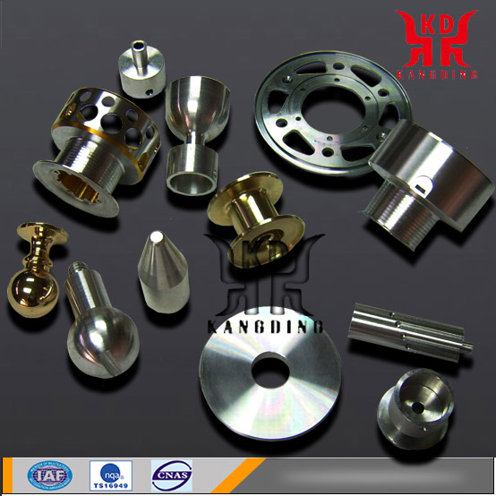
Shaft Machining

- PRODUCT DETAIL
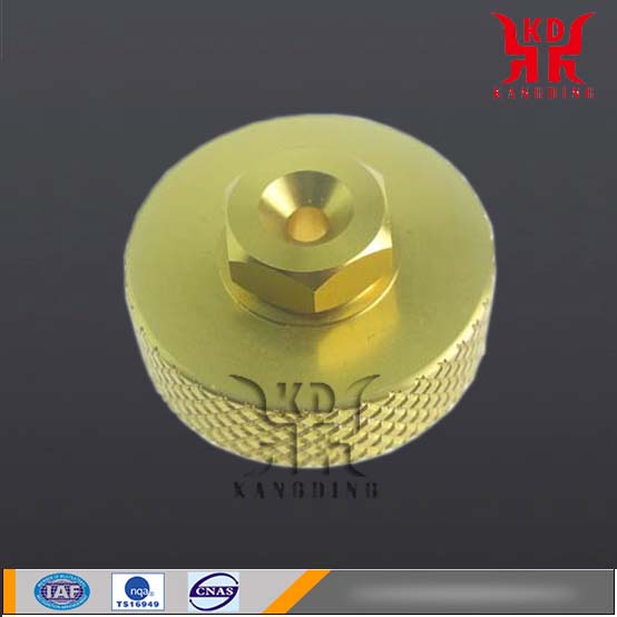
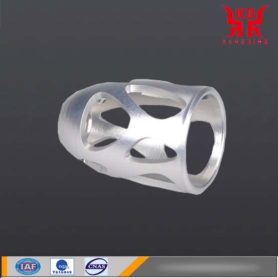
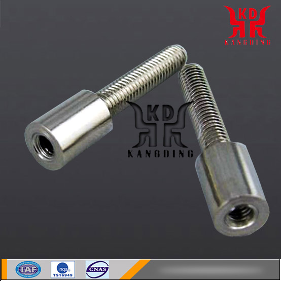
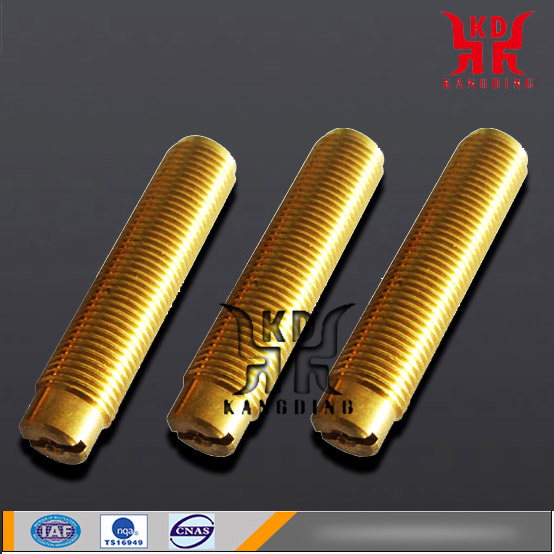
Shafts are mechanical parts that transmit motion, torque, or bending moments. Generally round metal rods, each segment can have different diameters.Motor shaft machining, stainless steel shaft machining, long shaft parts, precision shaft machining, small shaft machining, gear shaft machining, step shaft machining.
Technology
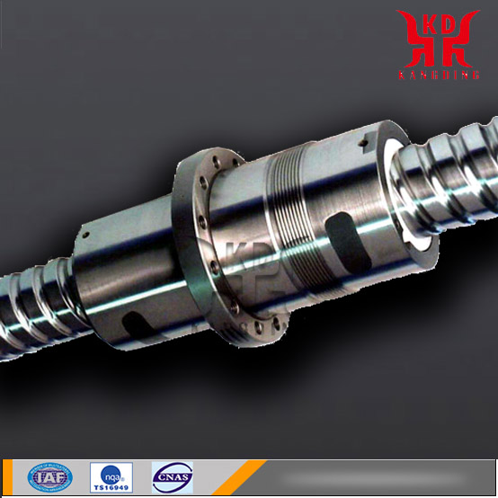
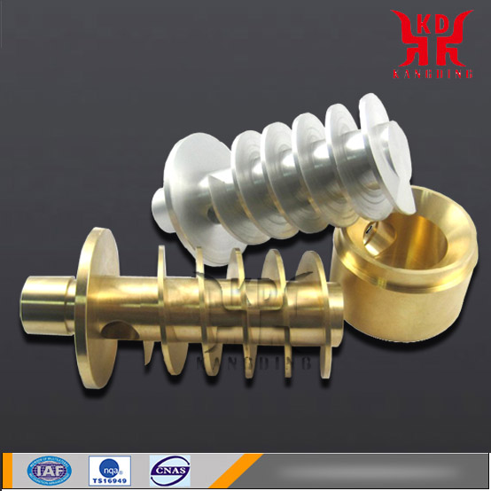
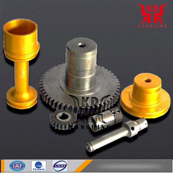
The product structure of the shaft is different. The shaft can be divided into a stepped shaft, a tapered mandrel, an optical shaft, a hollow shaft, a crankshaft, a camshaft, an eccentric shaft, various screw shafts, and the like.It is mainly used to support transmission parts, transmit torque and bear load. Shaft parts are rotating parts, whose length is greater than the diameter, generally consisting of the outer cylindrical surface, conical surface, inner bore and threads of the concentric shaft and the corresponding end face. According to different structural shapes, shaft parts can be divided into optical axis, stepped shaft, hollow shaft and crankshaft.
Shafts with an aspect ratio of less than 5 are called minor axes, and those with diameters greater than 20 are called elongated shafts, with most of the axes in between.
The basic production process is as follows:
1. Parts pattern analysis;
2. Determine the blank;
3. The method of determining the primary processing surface;
4. Determine the positioning benchmark;
5. Division phase
6. Heat treatment process arrangement;
7. Processing size and cutting amount;
8. Formulate the process;
9. Drive shaft machining process process diagram. Comprehensive analysis of the above:
Material
There are many types of shaft materials, and the selection is mainly based on the shaft strength, stiffness, wear resistance and other requirements, as well as the heat treatment method used to achieve these requirements, while taking into account the manufacturing process to be selected, and strive to economic and reasonable.
The common materials for shafts are high-quality carbon steels 35, 45, and 50. The most commonly used steels are 45 and 40Cr steels. For shafts with smaller loads, ordinary carbon steels such as Q235 or Q275 are also commonly used. For the shafts that require greater force, shaft size and weight are limited, and there are certain special requirements, alloy steel can be used, commonly used 40Cr, 40MnB, 40CrNi and so on. The material of the shaft is mainly carbon steel and alloy steel. Most of the steel shaft blanks use rolled steel and forgings, while others use direct round steel.
Ductile cast iron and some high-strength cast irons are easy to cast into complex shapes due to their good casting properties, as well as good vibration damping performance. Low sensitivity to stress concentration, the impact of the fulcrum displacement is small. Therefore, it is often used to manufacture complex-shaped shafts.
Camshaft material and heat treatment process (table)
| material | Preheat treatment | Final heat treatment | |||
| Technology | Hardness(HB) | Technology | Layer deep(mm) | Hardness(HB) | |
|
QT600-3 Alloy cast iron 45 |
Normalizing Stress relief annealing Conditioning |
229~302 241~302 187~229 |
Bainite austempering Bainite austempering nitrocarburizing Induction hardening |
0.1~0.15 3.0~6.0 |
43~50 >700HV kink 55~63 tooth 45~58 |
| 45QT600-3 |
Normalizing Stress relief annealing |
163~197 230~280 |
Induction hardening Bainite austempering |
2.5~5.5 |
kink 55~63 tooth 45~58 ≥45 |
| 20QT600-350 |
Stress relief annealing Normalizing |
≥170 |
Carburizing, quenching and tempering
Bainite austempering Induction quenching, tempering |
1.3~1.7 1.5~2.0 |
58~62 43~51 59~63 |
| 20CrMnTi | Normalizing | -- |
Carburizing, quenching and tempering
|
1.7~2.2 | 56~61 |
| 50Mn |
Annealing Stress relief annealing |
241~285 |
Induction hardening cam Bearing neck |
2~5 1.5~4 |
58~62 55~62 |
| 45 | Normalizing - | Induction quenching, tempering | 1.3~2.5 | 50~55 | |
Accuracy & Tolerance
Under normal circumstances, the shaft generally marked 0 ~ +0.005, if it is not often dismantled, it is +0.005 ~ +0.01 of the interference fit on it, if you often want to disassemble, To set the transition fit.
We also need to consider the thermal expansion of the shaft material itself during rotation, so the bigger the bearing, Clearance fit is preferably set to -0.005 ~ 0, not more than 0.01 at maximum.
H7H8h6 is a national standard shaft tolerances with the provisions of (uniform provisions to facilitate the exchange of drawings), The letters that begin with a capital letter (such as H7, K7, and Js7) indicate the hole tolerance, and the letters that begin with a lowercase letter (such as h7, k7, and js7) indicate the axis tolerance.
The tolerance level of the shaft or housing bore that matches the bearing is related to the accuracy of the bearing. For shafts fitted with P0-class precision bearings, the tolerance class is generally IT6, and the housing bore is generally IT7. For applications with high requirements for rotational accuracy and smoothness of operation (eg, motors, etc.), the shaft should be IT5 and the housing bore should be IT6.
Structural classification
The structural design of the shaft is an important step for the design of the shaft to determine the reasonable shape of the shaft and the overall size of the shaft. It consists of the type, size, and position of the mounting parts on the shaft, the fixing of the parts, the nature, direction, size, and distribution of the load. The type and size of the bearing, shaft blanks, manufacturing and assembly processes, installation and transport, and the shaft deformation and other factors. The designer can design according to the specific requirements of the shaft. If necessary, several options can be done for comparison. In order to select the design scheme, the following is the general shaft structure design principle:
1, save materials, reduce weight, as far as possible the use of equal-strength dimensions or large cross-sectional coefficient of the cross-sectional shape;
2, the shaft part is easy to pinpoint, solid, assembly, disassembly and adjustment;
3, the structure of various measures to reduce stress concentration and increase in strength;
4, to facilitate manufacturing and to ensure accuracy.
5. The nature, size, direction and distribution of the load;
6, shaft machining process and assembly methods.
7. The shaft and the parts mounted on the shaft must have an accurate working position;
Machining Process
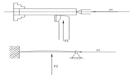
The shaft has poor rigidity during processing. When the cutting is affected by cutting force, gravity, cutting heat and other factors, bending deformation occurs, resulting in vibration, taper, drum shape and bamboo shape defects, it is difficult to ensure the processing accuracy. Through the analysis of the influence of various key technical problems of the slender shaft machining on the slender shaft machining, an improved method was found to improve the precision of slender shaft machining and ensure the pass rate. Drive shaft machining process:
Material preparation → Turning both ends, drilling center hole →Rough turning each outer circle→ quenching →Repair grinding center hole →Semi-precision turning of the outer circle, slot, chamfering →Thread→ Keying Groove Processing Line →Milling keyway→ Repair grinding center hole→ Grinding→ test.
Attention problem
Shaft parts need to pay attention to the surface roughness, mutual position accuracy, geometric accuracy, dimensional accuracy, etc... Processing and precautions:
(1) The order of machining of shaft parts should be based on "First base surface, First coarse, then fine grinding. " The principle arrangements.
(2) After machining the center hole for the main shaft part, first process the outer circle, then process the inner hole, and pay attention to the rough and fine processing separately.
(3) the deep hole processing is typically scheduled for after quenching. Because the deformation of the quenching and tempering treatment is large, it is difficult to correct the deep hole after it is bent and deformed.
(4) When processing the outer surface of the outer circle, the large diameter outer circle should be processed first, and then the small diameter outer circle should be processed. So as not to reduce the rigidity of the workpiece at the beginning.
(5) The machining of minor surfaces such as splines, keyways, etc. on the main shaft is generally performed after the outer fine wheel or rough grinding and before the rough grinding of the outer circle.
(6) Spindle threading is performed after the partial quenching of the spindle. The concentricity of the threaded surface and the supporting journal shaft is not affected by the deformation after quenching.
Shaft processing length to diameter ratio is not greater than 10CM, according to the blank size of machined parts ¥ 0.2 (price ¥ 5.00)
Ratio of length to diameter greater than 10 according to the general axis price * length to diameter ratio *1.15 quote
Accuracy requirements within 0.05MM or required taper Price quoted at the general optical axis base price*2
General stepped shaft (fan shaft, pump shaft, reducer shaft, grinding wheel shaft, motor shaft, spindle, etc.) with normal precision optical axis processing base price*2. Stepped shaft with taper and internal and external threads, according to the general accuracy of the optical axis processing base price * 3 offer
General purpose screw spindle processing by general accuracy base price * 4 quotes. General flange parts pricing according to material diameter * 0.07 quote, Diameter greater than 430MM according to the material diameter * 0.12
General round nut parts quoted by diameter *0.25 (including materials), General trapezoidal, triangular nut parts by diameter * 0.3 (not included material)
General sleeve type parts (diameter less than 100 diameter length less than 2), according to the material outer diameter *0.2.