Machining Technology of Large Diameter and Thin Wall Thread for Ti-6Al-4V Titanium Alloy Parts
Key words: Ti-6Al-4V titanium alloy parts, titanium alloy processing technology, large diameter Ti-6Al-4V titanium alloy parts, titanium alloy large diameter thin wall thread, titanium alloy thread turning
Ti-6Al-4V titanium alloy thin-walled tubular parts are shown in Figure 1: The thread diameter of the part is M320, the pitch is 4 mm, the wall thickness is only 3 mm, and the diameter to thickness ratio is 102. Moreover, the size and contour accuracy of the profile are required to be high, and the thread diameter has dimensional control requirements. Ti-6Al-4V titanium alloy has good plasticity and strong toughness, and has poor thermal conductivity. It is a difficult material to be processed, and its thin-walled characteristics make it difficult to control deformation during processing.
The titanium alloy large-diameter thread processing technology is still not mature, but its price is relatively expensive, and it is necessary to optimize the processing technology to ensure the production pass rate. For the turning of the thin-wall tubular part thread, this paper completes the design optimization of the tooling from the perspective of mechanical analysis and simulation. Combined with the tool wear test and the chip shape study, a reasonable combination of cutting parameters was obtained, and a suitable detection method was selected in combination with the thread detection results.
1, Selection of Feeding Way
For turning Ti-6Al-4V titanium alloy parts, because the workpiece material has good plasticity, the tool is required to have sufficient strength and toughness. Thread processing adopts KC5025, a threaded turning tool produced by Kenner Company, whose characteristics are shown in Table 1.
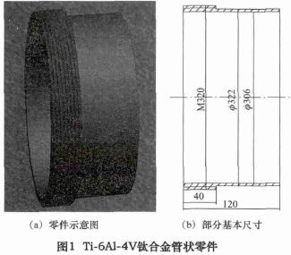
Ti-6Al-4V titanium alloy tubular parts drawing
Thread turning is a form of turning. Since the thread turning tool is in wedge contact with the tubular workpiece, the length of the cutting edge participating in the cutting is greatly increased as the cutting depth is increased. The main cutting edge and the minor cutting edge participate in the cutting at the same time, and the strong plasticity of the workpiece material makes the friction coefficient larger, so the turning condition of the tubular external thread processing of the titanium alloy is relatively bad. External thread turning usually uses the following three feeding methods (Figure 2):
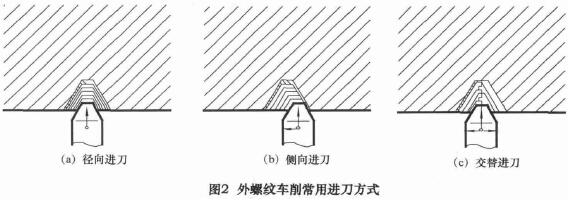
Figure 2: Common Feeding Ways for Turning Titanium Alloy External Thread
Table 1. Characteristics of Screw Turning Tool KC5025
(1) Radial feed: The feeding method is simple and V-shaped chips will be produced, which makes the control difficult.
(2) Lateral feed: Unilateral edge processing makes the cutting edge easy to wear and tear, which makes the accuracy of thread profile poor.
(3) Alternate feed: The tool life can be improved by alternating feeding along the two sides of the thread profile. It is suitable for cutting large pitch threads and requires special programming on NC machine tools. In the cutting test of large diameter thread processing, the radial feed method is adopted.
This method is most commonly used in thread turning, and its advantages are: The axial cutting force on both sides of the cutting edge of the threaded turning tool is offset, which can partly overcome the deflection caused by the axial cutting force in turning and reduce the profile error of the threads.
The disadvantages are: The cutting edges on both sides of the turning tool participate in the cutting at the same time, and the chips discharged on both sides will be squeezed together, and the chip discharging is difficult; At the same time, the force and heat of the thread turning tool are more serious, and the cutting edge is easy to wear; When the amount of the knife is large, it is easy to produce a "piercing knife" phenomenon, which is easy to damage the tool and affect the quality of the thread.
The amount of knife to be eaten should be gradually reduced, and the roughing, semi-finishing, and finishing should be degraded in stages. Cutting tool consumption should be gradually reduced, and for rough processing, semi-fine processing and finish processing, it should be reduced in stages. Since the turning tool is easy to wear, it is necessary to measure in the thread turning process.
2, mechanical analysis and tooling design
The thin-walled tubular thread turning has a large cutting force and a different component force in each direction. The cutting force on-line detection system can detect the component forces in the three directions of X, Y and Z during the machining process. The schematic diagram is shown in Figure 3. Combined with finite element simulation, the force deformation of the tubular part is analyzed, and the clamping condition of the workpiece is improved by the optimized design of the tooling.
2. 1 Mechanical Analysis of Thread Turning
When cutting with the grade KC5025 thread turning tool, the cutting depth of 0. 3 mm is used multiple times. In the case of high-speed cutting, the titanium alloy workpiece may undergo more severe oxidation phenomenon due to the heat of cutting, and the machining process becomes more difficult, so the cutting speed is less than 60 m/min. By using Kistler 9257B three-way dynamometer, the cutting force components with cutting depth of 0.3 m m and cutting speed of 20, 30, 40 and 50 m/min are obtained, as shown in Fig. 4.
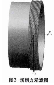
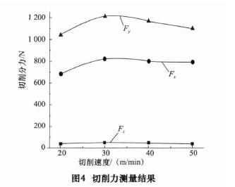
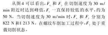 Fig. 4. Diagram of Cutting Force Fig. 4. Cutting force measurement result
As can be seen from Figure 4, F2 and F3 peaked at a cutting speed of around 30 m/min, and F2 remained at a low level, about 50 N. When the cutting speed was 30m / min, F2 and F3 respectively 822N and 1213N. During thread turning, F2 is in heavy duty cutting.
It can be stated that the radial internal support of the workpiece machining is not enough.
2. 2 tooling design optimization
Through the mechanical testing and processing deformation analysis, the conclusion is drawn: The tubular workpiece has a large radial deformation, and the internal support needs to be reinforced during the machining process. In the actual turning process, the deformation of the diameter of one end of the thread is about 0.03 mm, which has a certain verification effect on this conclusion. The optimized tooling is shown in Figure 6. The opening of the installation plate is conical, and the wedge ring and the pressing plate work together to make the contact state between the workpiece and the wedge ring better. It can ensure that the radial force of the workpiece is uniform during the thread processing, and the workpiece is supported by the wedge ring at different circumferential positions.
The original tooling has no wedge ring and pressure plate. The mounting portion is cylindrical, and there is a certain gap between the workpiece and the mounting plate during clamping, which causes residual stress and deformation.
The tooling in Figure 6 solves the problem of processing deformation well, and the diameter deformation of one end of the workpiece thread is reduced to 0.01 mm.
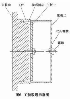
Image 6. Tooling improvement diagram
3, thread turning processing test
3. 1 tool wear test
Three different cutting speeds (15 m/min, 25 m/min, 35 m / min) were chosen. A complete thread is cut according to the determined radial feed and the tool wear is observed under a scanning electron microscope. The relationship between the degree of tool wear obtained by the test and the cutting speed is shown in Fig. 7.
Fig. 7 Tool wear at different cutting speeds
It can be seen from the test results that under the same conditions of the tool material, the tool wear increases rapidly with the increase of the cutting speed. When the cutting speed is 35 m/min during the actual machining of the thread, the tool life is approximately one thread processing time of the workpiece. When the cutting speed is slightly lowered, the tool life is improved and the thread surface quality is improved. For the thread turning of Ti-6Al-4V titanium alloy, it is more suitable to select a cutting speed of 30 m / min.
3. 2 Chip shape study
Through the turning test of Ti-6Al-4V titanium alloy external thread ( M320 mm × 4 mm). Thread processing is completed by multiple cutters. Cutting thickness is 0.75 mm, 0.30 mm, 0.20 mm, 0.15 mm, 0.10 mm, 0.075 mm and so on. Figure 9 shows the shape of the chip at different levels of the knife.
It can be seen that as the number of feeds increases, the amount of cuts decreases, and the amount of deformation of the chips decreases first and then increases. Moreover, when the chip deformation is small, large uneven deformation occurs on both sides of the V-shaped chip.
Therefore, the selection principle of the thread processing of the tubular workpiece is as follows: roughing knife amount > 0. 30 mm, finishing knife amount < 0. 15 mm. Through the tool wear test and the shape of the chip, the combination of the thread turning turning parameters of the tubular workpiece is determined as: The cutting speed of the finishing car is 30m / min, and the cutting tool is 0. 10 mm, which ensures the turning machining efficiency and improves the surface quality of the thread processing. The cutting speed of finish turning is 30 m/min and the cutting thickness is 0.10 mm, which ensures the turning efficiency and improves the surface quality of thread processing.
4, thread detection method
For three-needle measurement, three measuring needles with equal diameter and suitable size are placed in the corresponding spiral grooves on both sides of trapezoidal thread. Use a micrometer to measure the distance M between the apexes of the two needles. Then, the thread diameter value d2 is converted by the formula (2). The needle diameter should not be too large. It is necessary to ensure that the cross-section of the measuring needle is tangent to the side of the trapezoidal thread. If the diameter of the measuring needle is too small, the measuring needle will sink into the alveolar.
For a trapezoidal thread with a thread profile angle of 60°, the optimum value of the needle diameter d0 is d0 = 0. 577, P = 2. 308 mm.
After the processing of the external threads of the tubular workpiece is completed. Three needles plus external diameter micrometer and thread diameter micrometer are used to measure the diameter. And repeat the test with a high-precision coordinate measuring machine. The four sets of measurement results are shown in Table 2.
The thread inspection experiment shows: The error of the medium-diameter size measured by the three-needle plus the outer-diameter micrometer is small, and the error of the medium-diameter size measured directly by the thread-diameter micrometer is large, and the error reaches 0.01 mm. Therefore, the method of measuring with three needles and an outer diameter micrometer is more reasonable.
5. Conclusion
Through the research on the large diameter thread processing technology of Ti-6Al-4V titanium alloy, the following conclusions are drawn:
(1) The coated screw cutter KC5025 with the same hardness and toughness is used, and the tool is fed by the radial feed.
(2) Using the cutting force detection and the finite element simulation analysis method, the tooling design is optimized, and the diameter deformation during the threading process is reduced from 0.03 mm to 0.01 mm.
(3) The cutting speed for thread turning is 30 m/min, the amount of roughing is > 0. 30 mm, and the amount of finishing is < 0. 15 mm.
(4) Among the thread detection methods, the accuracy of the three-needle measurement is higher than that of the direct use of the thread diameter micrometer.
Ti-6Al-4V titanium alloy thin-walled tubular parts are shown in Figure 1: The thread diameter of the part is M320, the pitch is 4 mm, the wall thickness is only 3 mm, and the diameter to thickness ratio is 102. Moreover, the size and contour accuracy of the profile are required to be high, and the thread diameter has dimensional control requirements. Ti-6Al-4V titanium alloy has good plasticity and strong toughness, and has poor thermal conductivity. It is a difficult material to be processed, and its thin-walled characteristics make it difficult to control deformation during processing.
The titanium alloy large-diameter thread processing technology is still not mature, but its price is relatively expensive, and it is necessary to optimize the processing technology to ensure the production pass rate. For the turning of the thin-wall tubular part thread, this paper completes the design optimization of the tooling from the perspective of mechanical analysis and simulation. Combined with the tool wear test and the chip shape study, a reasonable combination of cutting parameters was obtained, and a suitable detection method was selected in combination with the thread detection results.
1, Selection of Feeding Way
For turning Ti-6Al-4V titanium alloy parts, because the workpiece material has good plasticity, the tool is required to have sufficient strength and toughness. Thread processing adopts KC5025, a threaded turning tool produced by Kenner Company, whose characteristics are shown in Table 1.
Ti-6Al-4V titanium alloy tubular parts drawing
Thread turning is a form of turning. Since the thread turning tool is in wedge contact with the tubular workpiece, the length of the cutting edge participating in the cutting is greatly increased as the cutting depth is increased. The main cutting edge and the minor cutting edge participate in the cutting at the same time, and the strong plasticity of the workpiece material makes the friction coefficient larger, so the turning condition of the tubular external thread processing of the titanium alloy is relatively bad. External thread turning usually uses the following three feeding methods (Figure 2):
Figure 2: Common Feeding Ways for Turning Titanium Alloy External Thread
Table 1. Characteristics of Screw Turning Tool KC5025
(1) Radial feed: The feeding method is simple and V-shaped chips will be produced, which makes the control difficult.
(2) Lateral feed: Unilateral edge processing makes the cutting edge easy to wear and tear, which makes the accuracy of thread profile poor.
(3) Alternate feed: The tool life can be improved by alternating feeding along the two sides of the thread profile. It is suitable for cutting large pitch threads and requires special programming on NC machine tools. In the cutting test of large diameter thread processing, the radial feed method is adopted.
This method is most commonly used in thread turning, and its advantages are: The axial cutting force on both sides of the cutting edge of the threaded turning tool is offset, which can partly overcome the deflection caused by the axial cutting force in turning and reduce the profile error of the threads.
The disadvantages are: The cutting edges on both sides of the turning tool participate in the cutting at the same time, and the chips discharged on both sides will be squeezed together, and the chip discharging is difficult; At the same time, the force and heat of the thread turning tool are more serious, and the cutting edge is easy to wear; When the amount of the knife is large, it is easy to produce a "piercing knife" phenomenon, which is easy to damage the tool and affect the quality of the thread.
The amount of knife to be eaten should be gradually reduced, and the roughing, semi-finishing, and finishing should be degraded in stages. Cutting tool consumption should be gradually reduced, and for rough processing, semi-fine processing and finish processing, it should be reduced in stages. Since the turning tool is easy to wear, it is necessary to measure in the thread turning process.
2, mechanical analysis and tooling design
The thin-walled tubular thread turning has a large cutting force and a different component force in each direction. The cutting force on-line detection system can detect the component forces in the three directions of X, Y and Z during the machining process. The schematic diagram is shown in Figure 3. Combined with finite element simulation, the force deformation of the tubular part is analyzed, and the clamping condition of the workpiece is improved by the optimized design of the tooling.
2. 1 Mechanical Analysis of Thread Turning
When cutting with the grade KC5025 thread turning tool, the cutting depth of 0. 3 mm is used multiple times. In the case of high-speed cutting, the titanium alloy workpiece may undergo more severe oxidation phenomenon due to the heat of cutting, and the machining process becomes more difficult, so the cutting speed is less than 60 m/min. By using Kistler 9257B three-way dynamometer, the cutting force components with cutting depth of 0.3 m m and cutting speed of 20, 30, 40 and 50 m/min are obtained, as shown in Fig. 4.
As can be seen from Figure 4, F2 and F3 peaked at a cutting speed of around 30 m/min, and F2 remained at a low level, about 50 N. When the cutting speed was 30m / min, F2 and F3 respectively 822N and 1213N. During thread turning, F2 is in heavy duty cutting.
It can be stated that the radial internal support of the workpiece machining is not enough.
2. 2 tooling design optimization
Through the mechanical testing and processing deformation analysis, the conclusion is drawn: The tubular workpiece has a large radial deformation, and the internal support needs to be reinforced during the machining process. In the actual turning process, the deformation of the diameter of one end of the thread is about 0.03 mm, which has a certain verification effect on this conclusion. The optimized tooling is shown in Figure 6. The opening of the installation plate is conical, and the wedge ring and the pressing plate work together to make the contact state between the workpiece and the wedge ring better. It can ensure that the radial force of the workpiece is uniform during the thread processing, and the workpiece is supported by the wedge ring at different circumferential positions.
The original tooling has no wedge ring and pressure plate. The mounting portion is cylindrical, and there is a certain gap between the workpiece and the mounting plate during clamping, which causes residual stress and deformation.
The tooling in Figure 6 solves the problem of processing deformation well, and the diameter deformation of one end of the workpiece thread is reduced to 0.01 mm.
Image 6. Tooling improvement diagram
3, thread turning processing test
3. 1 tool wear test
Three different cutting speeds (15 m/min, 25 m/min, 35 m / min) were chosen. A complete thread is cut according to the determined radial feed and the tool wear is observed under a scanning electron microscope. The relationship between the degree of tool wear obtained by the test and the cutting speed is shown in Fig. 7.
Fig. 7 Tool wear at different cutting speeds
It can be seen from the test results that under the same conditions of the tool material, the tool wear increases rapidly with the increase of the cutting speed. When the cutting speed is 35 m/min during the actual machining of the thread, the tool life is approximately one thread processing time of the workpiece. When the cutting speed is slightly lowered, the tool life is improved and the thread surface quality is improved. For the thread turning of Ti-6Al-4V titanium alloy, it is more suitable to select a cutting speed of 30 m / min.
3. 2 Chip shape study
Through the turning test of Ti-6Al-4V titanium alloy external thread ( M320 mm × 4 mm). Thread processing is completed by multiple cutters. Cutting thickness is 0.75 mm, 0.30 mm, 0.20 mm, 0.15 mm, 0.10 mm, 0.075 mm and so on. Figure 9 shows the shape of the chip at different levels of the knife.
It can be seen that as the number of feeds increases, the amount of cuts decreases, and the amount of deformation of the chips decreases first and then increases. Moreover, when the chip deformation is small, large uneven deformation occurs on both sides of the V-shaped chip.
Therefore, the selection principle of the thread processing of the tubular workpiece is as follows: roughing knife amount > 0. 30 mm, finishing knife amount < 0. 15 mm. Through the tool wear test and the shape of the chip, the combination of the thread turning turning parameters of the tubular workpiece is determined as: The cutting speed of the finishing car is 30m / min, and the cutting tool is 0. 10 mm, which ensures the turning machining efficiency and improves the surface quality of the thread processing. The cutting speed of finish turning is 30 m/min and the cutting thickness is 0.10 mm, which ensures the turning efficiency and improves the surface quality of thread processing.
4, thread detection method
For three-needle measurement, three measuring needles with equal diameter and suitable size are placed in the corresponding spiral grooves on both sides of trapezoidal thread. Use a micrometer to measure the distance M between the apexes of the two needles. Then, the thread diameter value d2 is converted by the formula (2). The needle diameter should not be too large. It is necessary to ensure that the cross-section of the measuring needle is tangent to the side of the trapezoidal thread. If the diameter of the measuring needle is too small, the measuring needle will sink into the alveolar.
For a trapezoidal thread with a thread profile angle of 60°, the optimum value of the needle diameter d0 is d0 = 0. 577, P = 2. 308 mm.
After the processing of the external threads of the tubular workpiece is completed. Three needles plus external diameter micrometer and thread diameter micrometer are used to measure the diameter. And repeat the test with a high-precision coordinate measuring machine. The four sets of measurement results are shown in Table 2.
The thread inspection experiment shows: The error of the medium-diameter size measured by the three-needle plus the outer-diameter micrometer is small, and the error of the medium-diameter size measured directly by the thread-diameter micrometer is large, and the error reaches 0.01 mm. Therefore, the method of measuring with three needles and an outer diameter micrometer is more reasonable.
5. Conclusion
Through the research on the large diameter thread processing technology of Ti-6Al-4V titanium alloy, the following conclusions are drawn:
(1) The coated screw cutter KC5025 with the same hardness and toughness is used, and the tool is fed by the radial feed.
(2) Using the cutting force detection and the finite element simulation analysis method, the tooling design is optimized, and the diameter deformation during the threading process is reduced from 0.03 mm to 0.01 mm.
(3) The cutting speed for thread turning is 30 m/min, the amount of roughing is > 0. 30 mm, and the amount of finishing is < 0. 15 mm.
(4) Among the thread detection methods, the accuracy of the three-needle measurement is higher than that of the direct use of the thread diameter micrometer.


