Instrument Lathe Processing Ball Valve Joint Outer Circle Hexagonal Part Method
This design uses a new type of four-way ball stop valve that is a hydraulic piping system for hydraulic supports in integrated mechanized coal mining equipment. The main features include a valve body, a lower valve seat, a spherical core, an upper valve seat, a compression nut, a shaft body and a sealing ring. A spherical globe valve structure is adopted in the valve, and the opening or closing of the liquid passage can be realized by rotating the handle by a 90 degree angle, and the existing plane ...
If the workpiece and the milling cutter rotate in the same direction at the same time on the lathe, how is the relative motion trajectory between them?
Here, you can tell in advance that it is a curve that is very close to a straight line. As shown in Figure 3.
Where h is the distance from point P to line QB. Using the analytical geometry method, the equation for h represented by the variable T can be obtained.
Derive it and let the derivative be zero.
d(h)/ d(T) =d(((b*con(B-nt)-x0)^2+( b*sin(B-nt))^2)^0.5)/ d(T)= 0
Solve it with a trial algorithm and get:
T=0.157 radians
The value of T, which is substituted into the equation, gives the maximum value of h.
H=0.056mm
This value is the non-straightness of the contour line on the cross section of the workpiece when machining the plane with a lathe (under four parameters R, r, L, n). This machining method is feasible if the resulting h is within the allowable tolerances.
The results obtained by the analytical method are very accurate, but multiple intermediate quantities need to be solved by the power equation of the trigonometric function. The solution process is cumbersome and complicated. We may wish to use the graphical method to get approximate results.
To determine the need for analytical methods.
II. Graphic method
We use the joint with the number QJ10-1 as an example.
The diameter of the milling cutter is R=120mm, the diameter of the workpiece blank is 30mm, and the final center distance between the milling cutter and the workpiece is set to L=73.5mm.
The angular velocity ratio of the milling cutter workpiece to the milling cutter is n=0.5.
According to the above parameters, the points A and B in Fig. 4 are obtained, which are 1, 12 points in the figure (Fig. 5).
Move 1 point to the 1' point by pressing the resolution graph.
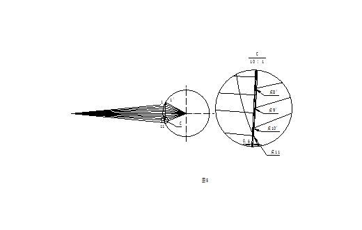
Dividing the 2A angle of the calibration in the analysis chart into 10 parts, Their intersection with the tool path circle is 1, 2, 3, 4, respectively. . . . . . ,12 o'clock, According to the method of analyzing the graph, go to the 1', 2', 3', ..., 10' points respectively. By connecting the points in a straight line, a line similar to the analytical curve can be obtained. It is not difficult to see in Figure 5 that the line of the line is very similar to the line connecting 1', 11. After zooming in 10 times, we will offset the line in parallel. When the distance between the two parallel lines is 0.06mm, the polyline has been fully included. That is to say, the shape error of this fold line and the straight line does not exceed 0.06 mm.
According to the provisions of the standard of MT419-1995 "Valve for hydraulic support", "the tolerance of machining in the drawing is not in accordance with the provisions of GB1184C". We look-up table of the machining plane flatness tolerance of 0.2mm. It can be seen that the theoretical error of the straight line of the busbar is still relatively small, and such a processing method is completely feasible.
We chose n=2, that is, the workpiece turns one turn and the milling cutter turns two turns. This means that the workpiece is rotated one turn and it is milled in two planes.
We designed the milling cutter into three blocks, and the workpiece was milled once in six planes.
At this point, all the theoretical problems have been solved.
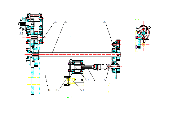
We use the CJ0640-A instrument lathe with high efficiency and single-station, and press the transmission development diagram to transform and realize the outer hexagonal processing of QJ10 spherical stop valve.
In the picture:
1.CJ0640A instrument lathe, 3 is the pulley of the original instrument lathe.
2. A newly added open drive mechanism attached to the headboard.
4. Drive shaft.
5. Rear drive mechanism.
After this series of transmissions, the ratio of the spindle to the milling cutter is guaranteed to be 2.
6. Universal joints,
7. Spline shaft,
8. Milling cutters and milling cutters.
9. The workpiece,
10. Fixtures.
The milling cutter holder is mounted on the small tool holder of the lathe. When the transverse feed is moved, the milling cutter moves on the spline shaft, and when the transverse feed is made, the universal joint is used to achieve a certain displacement.
Error Analysis of External Six Party Joint Parts of Instrument Lathe Processing Ball Valve
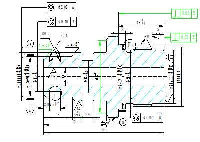
The joint is the main part of the ball stop valve, and the ball stop valve used on the hydraulic bracket has formed a series of products according to the size of the diameter. The structural elements of the Connector are identical. The figure below shows the joint part drawing of QJ-10:

As can be seen from the pattern, there is a 5mm long hexagon in the middle of the joint. For loading and unloading with a wrench. The most reasonable method for this part is to use hexagonal cold drawn steel. However, the material of the part is 45 steel, and the finished cold drawn steel on the market is difficult to find. Our company designs and processes, because its hexagonal section is only 1/10 of the total length of the parts. Increasing the cold drawing processing fee is not as economical as using Yuan Steel.
At present, our company's processing method is to first form the other parts of the part. Then, on the milling machine, two faces are machined by two three-sided edge milling cutters at a fixed distance, and then rotated twice to process two faces each. That is, there are three stations in the process. To produce a part, the jig is rotated twice, and two idle stroke. Processing efficiency is not high.
The production volume of joints is still relatively large, and the company's technicians are eager to find efficient processing methods. After investigation and demonstration, we decided to use instrument lathe to process the outer Six Party of the connector. The specific method is to add a rotating milling cutter on the guide rail of the instrument lathe, and machine the outer six sides by turning and milling.
We first demonstrate its feasibility in theory.
The basic knowledge of metal cutting tells us that the contour of a part is the relative motion of the cutting part of the tool and the workpiece.
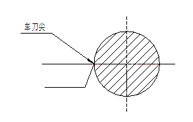
In the ordinary machining of a lathe, the turning tool does not move, the workpiece rotates, and the relative motion trajectory between them is a full circle equal to the diameter of the workpiece. Figure 1.

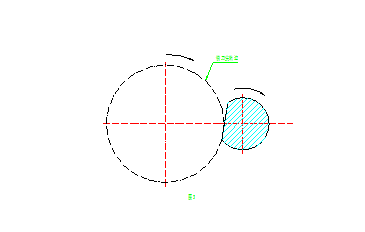
In the ordinary machining of the milling machine, the workpiece does not move, the milling cutter rotates, The relative motion trajectory between them is equal to: An arc of a point at which the edge of the milling cutter contacts the workpiece to the point at which the milling cutter tip leaves the workpiece.
As shown in Figure 2.
As shown in Figure 2.

If the workpiece and the milling cutter rotate in the same direction at the same time on the lathe, how is the relative motion trajectory between them?
Here, you can tell in advance that it is a curve that is very close to a straight line. As shown in Figure 3.

How is this curve formed, and how much it deviates from the shape of the line. We can use both analytical methods and mapping methods.
Analytical method
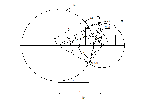
Figure 4 is an analytical diagram
Analytical method
Figure 4 is an analytical diagram

In the figure, circle 1 is the trajectory of the milling cutter tip. Circle 2 is the shape of the process blank
R The radius of the milling cutter tip
r workpiece blank radius
L milling cutter and workpiece center distance
n The angular velocity ratio of the workpiece to the tool, the value of which is ω workpiece / ω cutter
The four parameters listed above are chosen by the designer and are constants in the analytic expression.
Based on these four constants, the following constants can be calculated:
A=arccos((R^2+L^2-r^2)/2*R*L)
B=arcsin(sinA*r/R)
H=R*sinA
M=R*cosA
From the above constants, the following data can be derived:
Point A The point at which the tool starts to cut into the workpiece
Point B position The point at which the tool finally cuts the workpiece
The first point where the workpiece is cut is point A. When the tool rotates 2A degrees, it will go to point B. At the same time, the workpiece is rotated by 2nA degrees and then moved to the Q point. The Q point is still on the outer surface of the workpiece and is available.
Connecting Q and B in a straight line is the ideal straight line we want. However, the point cut by the tool from point A to point B is not on the straight line QB.
Below, we look for the analytical form of the workpiece point cut between the AB segments:
The tool is rotated from the point A to the point C, and the position of the point C can be determined by the distance b from the center point of the workpiece and the distance a from the horizontal axis of the workpiece center point. among them:
b=(R^2+L^2-2*R*L*con(A-T))^0.5
a=R*sin(A-T)
When the tool is rotated by t degrees to point B, the workpiece is rotated by nt angle to point P. P point is the knife
The relative trajectory point of the point on the workpiece cut at point C.
The center point of the workpiece is set as the coordinate origin, the horizontal axis is set to the x-axis, the right is the forward direction, the vertical axis is the y-axis, and the upper is the forward direction.
Can be derived:
x=-b*con(B-nt)
y=b*sin(B-nt)
Where t=2A-T
Using T as an argument, x, y are all functions of T, and the x expression of y can be obtained by collation. This is the analytical equation for the contour curve of the cross-section of the workpiece after milling.
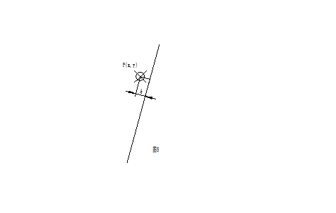
Fig. 4 is an explanatory diagram of the analytical method, but is drawn in actual scale in drawing. Thus, the point P in the figure appears to be on the straight line QB. Enlarge it as shown in Figure 5;

Where h is the distance from point P to line QB. Using the analytical geometry method, the equation for h represented by the variable T can be obtained.
Derive it and let the derivative be zero.
d(h)/ d(T) =d(((b*con(B-nt)-x0)^2+( b*sin(B-nt))^2)^0.5)/ d(T)= 0
Solve it with a trial algorithm and get:
T=0.157 radians
The value of T, which is substituted into the equation, gives the maximum value of h.
H=0.056mm
This value is the non-straightness of the contour line on the cross section of the workpiece when machining the plane with a lathe (under four parameters R, r, L, n). This machining method is feasible if the resulting h is within the allowable tolerances.
The results obtained by the analytical method are very accurate, but multiple intermediate quantities need to be solved by the power equation of the trigonometric function. The solution process is cumbersome and complicated. We may wish to use the graphical method to get approximate results.
To determine the need for analytical methods.
II. Graphic method
We use the joint with the number QJ10-1 as an example.
The diameter of the milling cutter is R=120mm, the diameter of the workpiece blank is 30mm, and the final center distance between the milling cutter and the workpiece is set to L=73.5mm.
The angular velocity ratio of the milling cutter workpiece to the milling cutter is n=0.5.
According to the above parameters, the points A and B in Fig. 4 are obtained, which are 1, 12 points in the figure (Fig. 5).
Move 1 point to the 1' point by pressing the resolution graph.

Dividing the 2A angle of the calibration in the analysis chart into 10 parts, Their intersection with the tool path circle is 1, 2, 3, 4, respectively. . . . . . ,12 o'clock, According to the method of analyzing the graph, go to the 1', 2', 3', ..., 10' points respectively. By connecting the points in a straight line, a line similar to the analytical curve can be obtained. It is not difficult to see in Figure 5 that the line of the line is very similar to the line connecting 1', 11. After zooming in 10 times, we will offset the line in parallel. When the distance between the two parallel lines is 0.06mm, the polyline has been fully included. That is to say, the shape error of this fold line and the straight line does not exceed 0.06 mm.
According to the provisions of the standard of MT419-1995 "Valve for hydraulic support", "the tolerance of machining in the drawing is not in accordance with the provisions of GB1184C". We look-up table of the machining plane flatness tolerance of 0.2mm. It can be seen that the theoretical error of the straight line of the busbar is still relatively small, and such a processing method is completely feasible.
We chose n=2, that is, the workpiece turns one turn and the milling cutter turns two turns. This means that the workpiece is rotated one turn and it is milled in two planes.
We designed the milling cutter into three blocks, and the workpiece was milled once in six planes.
At this point, all the theoretical problems have been solved.
We use the CJ0640-A instrument lathe with high efficiency and single-station, and press the transmission development diagram to transform and realize the outer hexagonal processing of QJ10 spherical stop valve.
In the picture:
1.CJ0640A instrument lathe, 3 is the pulley of the original instrument lathe.
2. A newly added open drive mechanism attached to the headboard.
4. Drive shaft.
5. Rear drive mechanism.
After this series of transmissions, the ratio of the spindle to the milling cutter is guaranteed to be 2.
6. Universal joints,
7. Spline shaft,
8. Milling cutters and milling cutters.
9. The workpiece,
10. Fixtures.
The milling cutter holder is mounted on the small tool holder of the lathe. When the transverse feed is moved, the milling cutter moves on the spline shaft, and when the transverse feed is made, the universal joint is used to achieve a certain displacement.


