How to stainless steel drilling? What should you pay attention to when drilling?
Twist drills are often used for drilling stainless steel workpieces. For hardened stainless steel, cemented carbide drills can be used, and super hard high speed steel or super fine grain cemented carbide drills can be used when conditions permit. When drilling, the torque and axial force are large, the chips are easy to bond, not easy to break, and it is difficult to remove chips. Work hardening is aggravated, the corner of the bit is easy to wear and tear, and the rigidity of the bit is poor, so it is easy to produce vibration. Therefore, the drill bit is required to grind out the chip groove, grind the cross edge to reduce the axial force, and grind into a double top angle to improve the heat dissipation conditions.

image 1. Stainless steel group drilling processing diagram

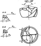
Figure 2 Stainless steel chip breaker bit

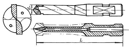
Figure 3. S-shaped carbide drill
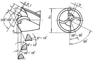
Typical drill bit for drilling stainless steel (I.e., stainless steel drilling group) As shown in Figure 1.

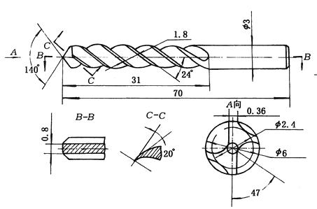
Image 4. Four-blade drill bit
In Fig. 3, L ≈ 0.32d0, L/2 > L1 > L / 3, R ≈ 0.2d0, h = 0.04d0, b ≈ 0.04d0. When drilling 1Cr18Ni9Ti stainless steel with this drill bit, For drills with diameters of 20 mm, 25 mm and 35 mm, four different feeds, n = 105 r/min, f = 0.32 mm/r, 0.4 mm/r, 0.56 mm/r and 0.67 mm/r, are adopted. The chip breaking and chip removal can be successfully carried out. Stainless steel chip breaking bit (fig. 2), S-shaped cemented carbide bit (fig. 3), four-edged belt bit (fig. 4) and indexable cemented carbide shallow hole drill can also be used. When machining martensitic stainless steel 2Crl3 with stainless steel chip breaker bit (Fig. 2), it is only necessary to grind the chipbreaker at E-E; When drilling lCrl8Ni9Ti austenitic stainless steel, it is necessary to open the chip breaker at A-A. The specific parameters of the stainless steel chip breaker bit and the applicable drilling amount are shown in Table 1.
The characteristics of the S-shaped carbide drill are: Without a chisel edge, the axial force can be reduced by 50%; The front corner of the core is positive and the edge is sharp; The thickness of drill core increases, and the rigidity of drill is increased; there are two cutting fluid holes. The arc-shaped cutting edge and the chip flute are distributed reasonably, which facilitates the chipping into small pieces for the discharge.
The characteristics of the indexable carbide shallow hole drill are: There are two convex triangular blades asymmetrically installed in the front of the bit. The different parts of the cutting hole can be automatically centered, the hole has good linearity and the length of cut-in and cut-out is short. The blade has a plurality of pit-shaped chipbreakers on the rake face, which has good cutting performance, especially the chip breaking is reliable, and the chips are consistently crushed; Internal cooling allows the cutting fluid to be sprayed directly onto the drilling surface to improve the cooling effect and the chip removal is very smooth; In particular, different grades of carbide inserts can be used according to the workpiece material, and the cutting speed is 80-120 m/min, and the drilling is very light.
The drilling amount of processed austenitic stainless steel is shown in Table 2.
When drilling stainless steel, it is often found that the drill bit is easy to wear and break, the surface of the hole is rough, and sometimes deep grooves are formed and cannot be eliminated; The aperture is too large, and the hole shape is not round or tilted to one side. Pay attention to the following when operating:
1. The geometry must be sharpened and the two cutting edges should be symmetrical. The excessive angle of the drill will result in the phenomenon of "pricking", causing chatter, and making the drilled holes polygonal. The chisel edge should be ground to reduce the axial force of the borehole.
2. bit must be installed to keep the drill sharp, and should be grinded in time after blunt.
3. Reasonable selection of bit geometry and drilling volume. According to the drilling depth requirements, the length of the drill bit should be shortened and the thickness of the core should be increased to increase the rigidity. When using a high speed steel drill bit, the cutting speed should not be too high to prevent the blade from being burned out. Feed should not be too large, in order to prevent worsening of drill bit or deviation of drill hole, feed should be adjusted appropriately when cutting in and out.
4. Fully cool and lubricate, the cutting fluid is generally suitable for vulcanized oil, the flow rate should not be less than 5 ~ 8 L / min, can not stop cooling in the middle. When the diameter is large, the internal cooling method should be used as much as possible.
5. Pay close attention to the drilling process, and observe the chip discharge condition in time. If the chip is found to be disorderly wound, immediately retract the knife to prevent the chip from being clogged. Attention should also be paid to the sound of the machine tool. If abnormalities are found, the tool should be retracted in time, and the drill bit should not be allowed to stay on the drilling surface to prevent the surface hardening of the drilling surface from increasing.

image 1. Stainless steel group drilling processing diagram

Figure 2 Stainless steel chip breaker bit

Figure 3. S-shaped carbide drill
Typical drill bit for drilling stainless steel (I.e., stainless steel drilling group) As shown in Figure 1.

Image 4. Four-blade drill bit
In Fig. 3, L ≈ 0.32d0, L/2 > L1 > L / 3, R ≈ 0.2d0, h = 0.04d0, b ≈ 0.04d0. When drilling 1Cr18Ni9Ti stainless steel with this drill bit, For drills with diameters of 20 mm, 25 mm and 35 mm, four different feeds, n = 105 r/min, f = 0.32 mm/r, 0.4 mm/r, 0.56 mm/r and 0.67 mm/r, are adopted. The chip breaking and chip removal can be successfully carried out. Stainless steel chip breaking bit (fig. 2), S-shaped cemented carbide bit (fig. 3), four-edged belt bit (fig. 4) and indexable cemented carbide shallow hole drill can also be used. When machining martensitic stainless steel 2Crl3 with stainless steel chip breaker bit (Fig. 2), it is only necessary to grind the chipbreaker at E-E; When drilling lCrl8Ni9Ti austenitic stainless steel, it is necessary to open the chip breaker at A-A. The specific parameters of the stainless steel chip breaker bit and the applicable drilling amount are shown in Table 1.
| Table 1. Set the chipbreaker and drilling amount of the stainless steel chip breaker bit | ||||||
|
Drill diameter d0 (mm) |
radius RE (mm) |
width BA (mm) |
radius RE (mm) |
width BE (mm) |
Spindle speed n (m/min) |
Feed amount f (mm/r) |
| >8~15 | 3.0~5.0 | 2.5~3.0 | 2.0~3.5 | 1.0~2.5 | 210~335 | 0.09~0.12 |
| >15~20 | 5.0~6.5 | 3.0~3.5 | 3.5~4.0 | 2.5~3.0 | 210~265 | |
| >20~25 | 6.5~7.5 | 3.5~4.5 | 4.0~4.5 | 2.8~3.3 | 170~210 | 0.12~0.14 |
| >25~30 | 7.5~8.5 | 4.5~5.0 | 4.5~5.0 | 3.0~3.5 | 132~170 | |
The characteristics of the S-shaped carbide drill are: Without a chisel edge, the axial force can be reduced by 50%; The front corner of the core is positive and the edge is sharp; The thickness of drill core increases, and the rigidity of drill is increased; there are two cutting fluid holes. The arc-shaped cutting edge and the chip flute are distributed reasonably, which facilitates the chipping into small pieces for the discharge.
The characteristics of the indexable carbide shallow hole drill are: There are two convex triangular blades asymmetrically installed in the front of the bit. The different parts of the cutting hole can be automatically centered, the hole has good linearity and the length of cut-in and cut-out is short. The blade has a plurality of pit-shaped chipbreakers on the rake face, which has good cutting performance, especially the chip breaking is reliable, and the chips are consistently crushed; Internal cooling allows the cutting fluid to be sprayed directly onto the drilling surface to improve the cooling effect and the chip removal is very smooth; In particular, different grades of carbide inserts can be used according to the workpiece material, and the cutting speed is 80-120 m/min, and the drilling is very light.
The drilling amount of processed austenitic stainless steel is shown in Table 2.
| Table 2. Drilling amount of austenitic stainless steel | ||
|
Drill diameter d0 (mm) |
Spindle speed n (m/min) |
Feed amount f (mm/r) |
| ≤5 | 1000~700 | 0.08~0.15 |
| >5~10 | 750~500 | |
| >10~15 | 600~400 | 0.12~0.25 |
| >15~20 | 450~200 | 0.15~0.35 |
| >20~30 | 400~150 | |
| >30~40 | 250~100 | 0.20~0.40 |
When drilling stainless steel, it is often found that the drill bit is easy to wear and break, the surface of the hole is rough, and sometimes deep grooves are formed and cannot be eliminated; The aperture is too large, and the hole shape is not round or tilted to one side. Pay attention to the following when operating:
1. The geometry must be sharpened and the two cutting edges should be symmetrical. The excessive angle of the drill will result in the phenomenon of "pricking", causing chatter, and making the drilled holes polygonal. The chisel edge should be ground to reduce the axial force of the borehole.
2. bit must be installed to keep the drill sharp, and should be grinded in time after blunt.
3. Reasonable selection of bit geometry and drilling volume. According to the drilling depth requirements, the length of the drill bit should be shortened and the thickness of the core should be increased to increase the rigidity. When using a high speed steel drill bit, the cutting speed should not be too high to prevent the blade from being burned out. Feed should not be too large, in order to prevent worsening of drill bit or deviation of drill hole, feed should be adjusted appropriately when cutting in and out.
4. Fully cool and lubricate, the cutting fluid is generally suitable for vulcanized oil, the flow rate should not be less than 5 ~ 8 L / min, can not stop cooling in the middle. When the diameter is large, the internal cooling method should be used as much as possible.
5. Pay close attention to the drilling process, and observe the chip discharge condition in time. If the chip is found to be disorderly wound, immediately retract the knife to prevent the chip from being clogged. Attention should also be paid to the sound of the machine tool. If abnormalities are found, the tool should be retracted in time, and the drill bit should not be allowed to stay on the drilling surface to prevent the surface hardening of the drilling surface from increasing.


