Design and Manufacture of Double-Blade End Mills - Milling of Steel Parts
With the continuous development of science and technology, in order to meet the special requirements of the performance of machine parts, some new materials with high strength, high toughness and high wear resistance are emerging. However, the cutting of these new materials has also raised new issues for the research of metal cutting tools. Their outstanding features in machining are: High strength, severe work hardening, poor surface quality, large cutting deformation, high cutting force, high cutting temperature, fast tool wear and difficulty in chip breaking. For example, in the high manganese material, after the plastic deformation, the austenite structure becomes a fine-grained martensite structure, and the processing hardness is increased from 180-220 HBS to 450-500 HBS, and the work hardening is severe; The depth of the chill layer can reach more than 0.3mm. In addition, the thermal conductivity of Gao Meng Steel is 0.25 times that of No. 45 steel, and the toughness is 8 times that of No. 45 steel. Not only the cutting force is increased, but also the chips are not easily broken. From the point of view of production and processing, in the use of indexable milling cutters. Due to the unreasonable selection of geometric parameters of the milling cutter, and the control of chip removal and chip breaking are not good, it often causes frequent knife-crushing in powerful milling. In addition, when the depth of the knife is large, the axial positioning is unreliable, which affects the promotion and application of the indexable milling cutter in difficult materials.
1. Angle selection
Milling contact state analysis The choice of milling angle is directly related to the milling contact state. Good milling contact state is one of the main problems in the selection of the powerful cutting cutter angle. As shown in Fig. 1, when the milling cutter cuts into the workpiece, the contact point between the rake face and the workpiece to be cut can be assumed to be four special points (U, V, S, T). According to the analysis, in order to prevent the chip from chipping, the starting point of contact should be selected at the point or point away from the main cutting edge, which is the best.
Selection of the depth of cut front angle gp and the feed front angle gf According to the above analysis, in order to make the initial contact point when the cutter is cut into the workpiece is U point or V point, the front angle selection of the milling cutter is crucial. When the feed rake angle gf is smaller than the cutter cutting angle d1, the longer the cutter cutting time, the slower the impact process when the cutter is cut. Thereby reducing the damage of the cutter caused by the thermal cracking of the cemented carbide milling cutter; The negative cutting depth rap angle gp can improve the impact resistance of the cutter. The negative feed rake angle gf can not only enhance the cutting edge strength, but also facilitate chip curling, breaking and elimination. Therefore, through analysis and experimental comparison, we chose the negative rake angle cutter angle, ie gp=-5°, gf=-8°.
Tool nose parameter selection Since the depth of cut and the feed front angle are both negative, the cutting deformation during milling is large, the cutting force is large, and the milling temperature is increased. Although strong cutting requires a large depth of cut and feed, the formation of wide and thick chips can reduce the temperature of the cutting zone, but it is also important to choose a reasonable angle. According to the processing requirements of strong cutting, considering the system stiffness and improving the heat dissipation conditions. Select the main declination kr=75° and, in order to increase the strength of the tip portion, this design adopts double secondary blade structure (Fig. 2), that is, grinding two sub-blades of kr1'=5° (blade length 2mm) and kr2'=15°. In addition, an arc having a tip radius re=1.5±0.1 mm is ground at the tip of the tool. This type of tool tip not only improves the tool strength, but also reduces the friction of the sub-back blade facing the machined surface, reduces the cutting force, reduces the cutting temperature, and improves the tool durability.
2. Structural analysis
Blade positioning method: The positioning of the blade on the knife pad not only meets the requirements of new blade positioning accuracy and reliability, but also ensures the positioning accuracy and reliability after the blade is indexed. This is an important principle for the selection of the positioning method of the blade and the positioning component design requirements. This design adopts the "three-point positioning" method, but considering that the powerful milling has larger cutting force than the general milling, the positioning point on the knife pad loses the positioning ability due to strong extrusion deformation, which affects the positioning accuracy and the positioning reliability. Therefore, a narrow and long face positioning structure is adopted on both sides of the blade. In order to improve the reliability of positioning, the positioning surface of the knife pad has strict requirements on the processing dimensional accuracy and positional accuracy. In order to control the end face of the cutting edge, the axial direction of the blade can be adjusted.
Clamping mechanism: The clamping mechanism is clamped by a front-pressure wedge. In order to meet the requirements of reliable clamping and convenient operation, the wedge angle of the wedge is selected to be 12°. If the clamping force point is at the upper part of the blade, a gap will be formed between the blade and the positioning surface of the blade, thereby deteriorating the positioning reliability of the blade. In order to avoid this phenomenon, the blade is tightly combined with the positioning surface of the blade, and the influence of the main cutting force (Fz) on the positioning accuracy of the blade can be overcome. The clamping force is selected at 1/2 of the blade and then 1 mm upward (Fj shown in Fig. 3), and the practice has proved to be effective.
Machining of milling pockets: Machining of milling pockets is one of the key processes in milling cutter manufacturing. It not only requires high machining accuracy of the sipe itself, but also requires high indexing accuracy between sipe. If the grading accuracy of the sipe is not high, the allowance will be uneven for the grooving. In order to control the amount of heat treatment deformation after quenching of the milling cutter, first, after the rough machining of the milling cutter body, the quenching and tempering treatment is performed to prepare the structure for quenching. The second is to use a graded quenching method to effectively avoid heat treatment deformation and cracking. In order to improve the accuracy of the sipe indexing, the special groove for the grinding groove is used in the grinding groove process to ensure the design requirements of the sipe manufacturing precision and the indexing accuracy.
3. Dosage selection
According to the cutting characteristics of difficult-to-machine materials, when milling high-manganese steel, hardened steel, chilled cast iron and other materials, especially for powerful milling of steel parts, the choice of milling dosage is generally: The milling speed is slightly lower to reduce the milling temperature, reduce tool wear and improve tool durability; the milling depth and feed rate are appropriately increased to ensure that the tool exceeds the depth of the work hardened layer and reduces tool wear and chipping.
However, it is also necessary to consider that the milling force increases due to the increased milling depth and feed rate, causing vibrations in the milling process and the problem that the chips are not easily broken.
4. Milling experiments
Experimental condition
Machine tool: X5020;
Workpiece: ZGMn13 180~200HB
Milling cutter: d0=315 z=16 YT798 double secondary edge end milling cutter;
Dosage: Vc = 25 m / min ap fz = 0.2 mm / z.
Experimental results 96 pieces of workpiece were continuously milled, and two shifts were milled without abnormal wear such as chipping, knife cutting and hot cracking. Compared with other milling cutters, the productivity is improved by nearly 3 times and the tool durability is increased by 1.5 times.
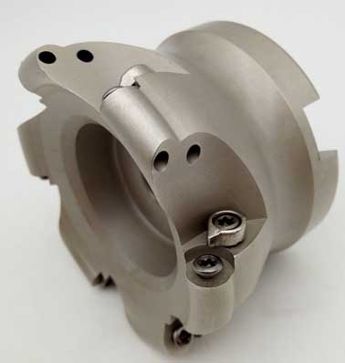
The double-blade powerful end milling cutter has reasonable parameters and structure, reliable clamping and positioning, large milling amount, good rigidity, high production efficiency and long tool life. It is especially suitable for roughing and semi-finishing of difficult-to-machine materials such as high manganese steel, hardened steel and high alloy steel. At the tool cutting exhibition organized by the National Knife Association, the double-blade powerful milling cutter was well received when processing high-manganese steel materials. It has been widely used in large enterprises such as Second Automobile and Dalian Diesel Engine Factory.
1. Angle selection
Milling contact state analysis The choice of milling angle is directly related to the milling contact state. Good milling contact state is one of the main problems in the selection of the powerful cutting cutter angle. As shown in Fig. 1, when the milling cutter cuts into the workpiece, the contact point between the rake face and the workpiece to be cut can be assumed to be four special points (U, V, S, T). According to the analysis, in order to prevent the chip from chipping, the starting point of contact should be selected at the point or point away from the main cutting edge, which is the best.
Selection of the depth of cut front angle gp and the feed front angle gf According to the above analysis, in order to make the initial contact point when the cutter is cut into the workpiece is U point or V point, the front angle selection of the milling cutter is crucial. When the feed rake angle gf is smaller than the cutter cutting angle d1, the longer the cutter cutting time, the slower the impact process when the cutter is cut. Thereby reducing the damage of the cutter caused by the thermal cracking of the cemented carbide milling cutter; The negative cutting depth rap angle gp can improve the impact resistance of the cutter. The negative feed rake angle gf can not only enhance the cutting edge strength, but also facilitate chip curling, breaking and elimination. Therefore, through analysis and experimental comparison, we chose the negative rake angle cutter angle, ie gp=-5°, gf=-8°.
Tool nose parameter selection Since the depth of cut and the feed front angle are both negative, the cutting deformation during milling is large, the cutting force is large, and the milling temperature is increased. Although strong cutting requires a large depth of cut and feed, the formation of wide and thick chips can reduce the temperature of the cutting zone, but it is also important to choose a reasonable angle. According to the processing requirements of strong cutting, considering the system stiffness and improving the heat dissipation conditions. Select the main declination kr=75° and, in order to increase the strength of the tip portion, this design adopts double secondary blade structure (Fig. 2), that is, grinding two sub-blades of kr1'=5° (blade length 2mm) and kr2'=15°. In addition, an arc having a tip radius re=1.5±0.1 mm is ground at the tip of the tool. This type of tool tip not only improves the tool strength, but also reduces the friction of the sub-back blade facing the machined surface, reduces the cutting force, reduces the cutting temperature, and improves the tool durability.
2. Structural analysis
Blade positioning method: The positioning of the blade on the knife pad not only meets the requirements of new blade positioning accuracy and reliability, but also ensures the positioning accuracy and reliability after the blade is indexed. This is an important principle for the selection of the positioning method of the blade and the positioning component design requirements. This design adopts the "three-point positioning" method, but considering that the powerful milling has larger cutting force than the general milling, the positioning point on the knife pad loses the positioning ability due to strong extrusion deformation, which affects the positioning accuracy and the positioning reliability. Therefore, a narrow and long face positioning structure is adopted on both sides of the blade. In order to improve the reliability of positioning, the positioning surface of the knife pad has strict requirements on the processing dimensional accuracy and positional accuracy. In order to control the end face of the cutting edge, the axial direction of the blade can be adjusted.
Clamping mechanism: The clamping mechanism is clamped by a front-pressure wedge. In order to meet the requirements of reliable clamping and convenient operation, the wedge angle of the wedge is selected to be 12°. If the clamping force point is at the upper part of the blade, a gap will be formed between the blade and the positioning surface of the blade, thereby deteriorating the positioning reliability of the blade. In order to avoid this phenomenon, the blade is tightly combined with the positioning surface of the blade, and the influence of the main cutting force (Fz) on the positioning accuracy of the blade can be overcome. The clamping force is selected at 1/2 of the blade and then 1 mm upward (Fj shown in Fig. 3), and the practice has proved to be effective.
Machining of milling pockets: Machining of milling pockets is one of the key processes in milling cutter manufacturing. It not only requires high machining accuracy of the sipe itself, but also requires high indexing accuracy between sipe. If the grading accuracy of the sipe is not high, the allowance will be uneven for the grooving. In order to control the amount of heat treatment deformation after quenching of the milling cutter, first, after the rough machining of the milling cutter body, the quenching and tempering treatment is performed to prepare the structure for quenching. The second is to use a graded quenching method to effectively avoid heat treatment deformation and cracking. In order to improve the accuracy of the sipe indexing, the special groove for the grinding groove is used in the grinding groove process to ensure the design requirements of the sipe manufacturing precision and the indexing accuracy.
3. Dosage selection
According to the cutting characteristics of difficult-to-machine materials, when milling high-manganese steel, hardened steel, chilled cast iron and other materials, especially for powerful milling of steel parts, the choice of milling dosage is generally: The milling speed is slightly lower to reduce the milling temperature, reduce tool wear and improve tool durability; the milling depth and feed rate are appropriately increased to ensure that the tool exceeds the depth of the work hardened layer and reduces tool wear and chipping.
However, it is also necessary to consider that the milling force increases due to the increased milling depth and feed rate, causing vibrations in the milling process and the problem that the chips are not easily broken.
4. Milling experiments
Experimental condition
Machine tool: X5020;
Workpiece: ZGMn13 180~200HB
Milling cutter: d0=315 z=16 YT798 double secondary edge end milling cutter;
Dosage: Vc = 25 m / min ap fz = 0.2 mm / z.
Experimental results 96 pieces of workpiece were continuously milled, and two shifts were milled without abnormal wear such as chipping, knife cutting and hot cracking. Compared with other milling cutters, the productivity is improved by nearly 3 times and the tool durability is increased by 1.5 times.
The double-blade powerful end milling cutter has reasonable parameters and structure, reliable clamping and positioning, large milling amount, good rigidity, high production efficiency and long tool life. It is especially suitable for roughing and semi-finishing of difficult-to-machine materials such as high manganese steel, hardened steel and high alloy steel. At the tool cutting exhibition organized by the National Knife Association, the double-blade powerful milling cutter was well received when processing high-manganese steel materials. It has been widely used in large enterprises such as Second Automobile and Dalian Diesel Engine Factory.


