Design Analysis of Progressive Stamping Die for Q235 Carbon Structural Steel Triangle Gasket
1. Process analysis of blanking parts
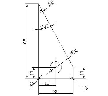
Workpiece name: triangular gasket stamping, progressive stamping die
Workpiece sketch: as shown in Figure 1-1
Production batch: annual output of 1 million pieces for general batch
Material: Q235
Material thickness 0.5mm
1.1 stamping material
Q235 is a common carbon structural steel with general strength, good plasticity, weldability and pressure processing. It is mainly used for engineering structures and mechanical parts with less stress, and can be punched out.
1.2 workpiece structure shape
The shape of the workpiece is relatively simple, the size is not large, it is triangular, the inner shape has no sharp angle, and the distance between the hole and the edge also meets the requirements, which is suitable for punching processing. In addition to a large hole of φ10, the punching part has a production program of 200,000 pieces, which belongs to the general batch. It should pay attention to the choice of mold materials and the choice of structure to ensure a certain die life.
1.3 dimensional accuracy
The unmarked tolerance on the part drawing is IT13, the dimensional accuracy requirement is low, and ordinary progressive punching can fully meet the requirements.
According to the above analysis: the punching characteristics of the part, suitable for progressive blanking.
2. Determination of the punching process plan
The stamping process required for this part is the two basic processes of blanking and punching. There are three process options:
Option One:
Punching first, then blanking; single-step mold production.
Option II:
Punching - blanking composite stamping; composite mould production.
Option three:
Punching - blanking progressive stamping; progressive die production.
Combined with mold design and mass production analysis:
The scheme 1 has a simple mold structure, short manufacturing cycle and simple manufacture, but requires two pairs of molds, and has high cost and low production efficiency, and is difficult to meet the requirements of mass production.
Solution 3 only needs one pair of molds, which has high production efficiency, convenient operation and accuracy, but the mold has large contour size, complicated manufacturing and high cost.
In the second scheme, only one pair of molds is needed, and the precision of the parts and the production efficiency are high, and the minimum wall thickness of the workpiece is larger than that of the convex and concave molds, and the minimum wall thickness of the mold can also meet the requirements.
The relative positional accuracy of the inner hole and the edge of the blanking part is relatively high, the contour size of the mold is small, the manufacturing mold is simpler than the scheme 3, and the positioning accuracy of the sheet material is lower than that of the third scheme.
Through the analysis and comparison of the above three schemes, the stamping production of the workpiece is preferably the second scheme.
3, process calculation
3.1, the pressing force is calculated
The elastic unloading device and the flip-chip composite blanking die are used, and the pressing force is the sum of the punching force, the unloading force, and the recommended force.
1) Calculation of punching force
When punching with a flat blade, the punching force F is generally calculated as follows: F = Ltτb
Where F-punching force;
L—the circumference of the blanking piece;
T—material thickness;
Τb—the shear strength of the material;
K-coefficient, coefficient K is given the correction factor considering the influence of the fluctuation and unevenness of the mold gap value, the edge wear, the mechanical properties of the sheet and the thickness fluctuation, etc., and generally takes K=1.3.
Calculate the contour perimeter L of the blanking piece, L = a + b + c + d (Equation 5-4)
Where a, b, c, d—the length of the blanked part; L=65+30+10+63=168(mm)
Check 2-1 to take τb=450Mpa
F=Ltτb=168×0.5×450=37.8(KN)
2),
Calculation of stripping force, driving force
Discharge force FX FX=KXF (Equation 5-5)
Push force FT FT =nKTF (Equation 5-6)
n~ the number of parts or scraps in the indented mold (n=h/t);
h~the height of the straight edge portion (mm);
t~ material thickness (mm)
FX=KXF=0.045×37800=1.701(KN)
(KX, KT are stripping force, driving force coefficient, the value of which can be found in Table 5-3)
FT=nKTF = 12 × 0.063 × 37800 = 28.576 (KN)
Therefore, the total punching pressure FZ=F+FX+FT=37.8+1.701+28.576=68.077(KN)
2, primary press
According to the calculation results of the pressing pressure, the press specification is J23-10 press.
Table 5-3 stripping force, driving force and top force coefficient
3. Layout design and material utilization analysis
1), the choice of layout method
Option 1: There is a waste typesetting, which is punched along the shape of the punching piece, and there are edges on the periphery of the punching piece. The size of the punch is completely guaranteed by the die, so the punching accuracy is high, the die life is high, but the material utilization rate is low.
Option 2: Less waste typesetting, Due to the influence of shear strip and positioning error, the quality of the punch is poor, and the die life is lower than that of the scheme 1, but the material utilization rate is slightly higher, and the die structure is simple.
Option 3: No waste typesetting, the quality of the stampings and die life is lower, but the material utilization rate is the highest.
Through the analysis and comparison of the above three schemes, considering the life of the mold and the quality of the punching piece, the selection method 3 of the punching method of the punching piece is better. Considering the mold structure and manufacturing cost, the specific form of waste layout is optimal.
2) Calculate the strip width
The function of the edge is to compensate for the positioning error and keep the strip a certain rigidity to ensure the quality of the parts and the convenient feeding. Take the edge is too large, a waste material. When the edge is too small, it is easy to warp or be broken when punching, which not only increases the burr of the punching part, but also damages the cutting edge of the die in the gap between the convex and the concave die, and reduces the life of the die. Or affect the feeding work. The edge value is usually determined by experience. The edge value listed in Table 4 is one of the empirical data for ordinary punching.
The shape of the part, take the boundary values of a = 1.0mm between the workpiece 4 look-up table, take the boundary values a1 = 1.2mm between the workpiece and sides. The strip material is obtained by cutting the blank material. In order to ensure smooth feeding, the deviation is zero, and the small deviation is negative value-△
B=(Dmax+2a)-0△ ((Equation 5-1))
Where Dmax—the maximum size of the blanking member in the width direction of the strip;
A— the edge value between the blanks;
△—the deviation of the sheet trimming (the value is shown in Table 5-2);
B=(30.1+2×3)=32.40-0.5(mm)
Table 5-1 Numerical values take the edge and side of the value
3), determine Step distance
Feed Distance S: The distance each time the strip is fed on the mold is called the Step Distance, and each Step distance can punch one or more parts.
The distance is related to the layout method and is the basis for determining the position of the stopper pin.
The determination of the width of the strip is related to the structure of the mold.
The principle of determining the distance is that the minimum strip width is to ensure that there is sufficient edge value around the workpiece during punching;
The maximum strip width can smoothly feed the strip between the guide plates during punching and has a certain gap.
Feeding step S = 30 + 1.2 = 31.2 (mm)
The layout is shown in Figure 5-2.
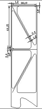
Figure 5-2 Layout
4), the specification of sheet material is 1500mmx3000mmx0.5mm
5), strip length L = 1500mm
6), the number of strips that can be cut per material
3000/46.3=64.79.
7), the number of parts that can be punched out per strip
n=1500/61.4=22.2
8), the number of parts that can be punched out per material
64x22=1408
9), A strip of material utilization
22x65x43.63/1500x46.3=89.83%
10), material utilization of a sheet
1408x65x42.2/1500x3000=85.8%
The percentage of the actual area of the blank and the area of the sheet used is called the utilization of the material. It is an important indicator for measuring the rational use of materials.
Material utilization within a Step Distance
η=A/BS×100% (formula 5-2)
Where A is the actual area of the blanking member within a step;
B— the width of the strip;
S— step distance;
η=70x30+0.5×30×55/46.03×31.2×100%=89.03%
4. Determination of mold pressure center
The mold pressure center refers to the position of the action point of the combined pressure of the punching force during pressing. To ensure proper operation of the press and mold, the pressure center of the mold should coincide with the center of the press slide. Otherwise, the die and the press slider will produce an eccentric load, causing excessive friction between the slider and the guide rail, and the mold guiding parts will accelerate wear and reduce the service life of the mold and the press. The parts is a triangular figure whose center is the center of pressure.
Workpiece name: triangular gasket stamping, progressive stamping die
Workpiece sketch: as shown in Figure 1-1
Production batch: annual output of 1 million pieces for general batch
Material: Q235
Material thickness 0.5mm
1.1 stamping material
Q235 is a common carbon structural steel with general strength, good plasticity, weldability and pressure processing. It is mainly used for engineering structures and mechanical parts with less stress, and can be punched out.
1.2 workpiece structure shape
The shape of the workpiece is relatively simple, the size is not large, it is triangular, the inner shape has no sharp angle, and the distance between the hole and the edge also meets the requirements, which is suitable for punching processing. In addition to a large hole of φ10, the punching part has a production program of 200,000 pieces, which belongs to the general batch. It should pay attention to the choice of mold materials and the choice of structure to ensure a certain die life.
1.3 dimensional accuracy
The unmarked tolerance on the part drawing is IT13, the dimensional accuracy requirement is low, and ordinary progressive punching can fully meet the requirements.
According to the above analysis: the punching characteristics of the part, suitable for progressive blanking.
2. Determination of the punching process plan
The stamping process required for this part is the two basic processes of blanking and punching. There are three process options:
Option One:
Punching first, then blanking; single-step mold production.
Option II:
Punching - blanking composite stamping; composite mould production.
Option three:
Punching - blanking progressive stamping; progressive die production.
Combined with mold design and mass production analysis:
The scheme 1 has a simple mold structure, short manufacturing cycle and simple manufacture, but requires two pairs of molds, and has high cost and low production efficiency, and is difficult to meet the requirements of mass production.
Solution 3 only needs one pair of molds, which has high production efficiency, convenient operation and accuracy, but the mold has large contour size, complicated manufacturing and high cost.
In the second scheme, only one pair of molds is needed, and the precision of the parts and the production efficiency are high, and the minimum wall thickness of the workpiece is larger than that of the convex and concave molds, and the minimum wall thickness of the mold can also meet the requirements.
The relative positional accuracy of the inner hole and the edge of the blanking part is relatively high, the contour size of the mold is small, the manufacturing mold is simpler than the scheme 3, and the positioning accuracy of the sheet material is lower than that of the third scheme.
Through the analysis and comparison of the above three schemes, the stamping production of the workpiece is preferably the second scheme.
3, process calculation
3.1, the pressing force is calculated
The elastic unloading device and the flip-chip composite blanking die are used, and the pressing force is the sum of the punching force, the unloading force, and the recommended force.
1) Calculation of punching force
When punching with a flat blade, the punching force F is generally calculated as follows: F = Ltτb
Where F-punching force;
L—the circumference of the blanking piece;
T—material thickness;
Τb—the shear strength of the material;
K-coefficient, coefficient K is given the correction factor considering the influence of the fluctuation and unevenness of the mold gap value, the edge wear, the mechanical properties of the sheet and the thickness fluctuation, etc., and generally takes K=1.3.
Calculate the contour perimeter L of the blanking piece, L = a + b + c + d (Equation 5-4)
Where a, b, c, d—the length of the blanked part; L=65+30+10+63=168(mm)
Check 2-1 to take τb=450Mpa
F=Ltτb=168×0.5×450=37.8(KN)
2),
Calculation of stripping force, driving force
Discharge force FX FX=KXF (Equation 5-5)
Push force FT FT =nKTF (Equation 5-6)
n~ the number of parts or scraps in the indented mold (n=h/t);
h~the height of the straight edge portion (mm);
t~ material thickness (mm)
FX=KXF=0.045×37800=1.701(KN)
(KX, KT are stripping force, driving force coefficient, the value of which can be found in Table 5-3)
FT=nKTF = 12 × 0.063 × 37800 = 28.576 (KN)
Therefore, the total punching pressure FZ=F+FX+FT=37.8+1.701+28.576=68.077(KN)
2, primary press
According to the calculation results of the pressing pressure, the press specification is J23-10 press.
Table 5-3 stripping force, driving force and top force coefficient
|
Thicknesst/mm |
KX |
KT |
KD |
|
|
steel |
≤0.1 >0.1~0.5 >0.5~2.5 >2.5~6.5 >6.5 |
0.065~0.075 0.045~0.055 0.04~0.05 0.03~0.04 0.02~0.03 |
0.1 0.063 0.055 0.045 0.025 |
0.14 0.08 0.06 0.05 0.03 |
|
Aluminum, aluminum alloy Pure copper, brass |
0.025~0.08 0.02~0.06 |
0.03~0.07 0.03~0.09 |
||
3. Layout design and material utilization analysis
1), the choice of layout method
Option 1: There is a waste typesetting, which is punched along the shape of the punching piece, and there are edges on the periphery of the punching piece. The size of the punch is completely guaranteed by the die, so the punching accuracy is high, the die life is high, but the material utilization rate is low.
Option 2: Less waste typesetting, Due to the influence of shear strip and positioning error, the quality of the punch is poor, and the die life is lower than that of the scheme 1, but the material utilization rate is slightly higher, and the die structure is simple.
Option 3: No waste typesetting, the quality of the stampings and die life is lower, but the material utilization rate is the highest.
Through the analysis and comparison of the above three schemes, considering the life of the mold and the quality of the punching piece, the selection method 3 of the punching method of the punching piece is better. Considering the mold structure and manufacturing cost, the specific form of waste layout is optimal.
2) Calculate the strip width
The function of the edge is to compensate for the positioning error and keep the strip a certain rigidity to ensure the quality of the parts and the convenient feeding. Take the edge is too large, a waste material. When the edge is too small, it is easy to warp or be broken when punching, which not only increases the burr of the punching part, but also damages the cutting edge of the die in the gap between the convex and the concave die, and reduces the life of the die. Or affect the feeding work. The edge value is usually determined by experience. The edge value listed in Table 4 is one of the empirical data for ordinary punching.
The shape of the part, take the boundary values of a = 1.0mm between the workpiece 4 look-up table, take the boundary values a1 = 1.2mm between the workpiece and sides. The strip material is obtained by cutting the blank material. In order to ensure smooth feeding, the deviation is zero, and the small deviation is negative value-△
B=(Dmax+2a)-0△ ((Equation 5-1))
Where Dmax—the maximum size of the blanking member in the width direction of the strip;
A— the edge value between the blanks;
△—the deviation of the sheet trimming (the value is shown in Table 5-2);
B=(30.1+2×3)=32.40-0.5(mm)
Therefore, the width of the strip 32.4 ~ 32.9mm
|
Material thickness t |
Round pieces and r>2t rounded corners | Rectangular side length l ≤ 50 | Rectangular side length l>50 or rounded corner r≤2 | |||
| A1 between workpieces | Side a | A between workpieces | Side a1 | A1 between workpieces | Side a | |
| 0.25以下 | 1.8 | 2.0 | 2.2 | 2.5 | 2.8 | 3.0 |
| 0.25~0.5 | 1.2 | 1.5 | 1.8 | 2.0 | 2.2 | 2.5 |
| 0.5~0.8 | 1.0 | 1.2 | 1.5 | 1.8 | 1.8 | 2.0 |
| 0.8~1.2 | 0.8 | 1.0 | 1.2 | 1.5 | 1.5 | 1.8 |
| 1.2~1.5 | 1.0 | 1.2 | 1.5 | 1.8 | 1.9 | 2.0 |
| 1.6~2.0 | 1.2 | 1.5 | 2.0 | 2.2 | 2.0 | 2.2 |
3), determine Step distance
Feed Distance S: The distance each time the strip is fed on the mold is called the Step Distance, and each Step distance can punch one or more parts.
The distance is related to the layout method and is the basis for determining the position of the stopper pin.
The determination of the width of the strip is related to the structure of the mold.
The principle of determining the distance is that the minimum strip width is to ensure that there is sufficient edge value around the workpiece during punching;
The maximum strip width can smoothly feed the strip between the guide plates during punching and has a certain gap.
Feeding step S = 30 + 1.2 = 31.2 (mm)
The layout is shown in Figure 5-2.
Figure 5-2 Layout
4), the specification of sheet material is 1500mmx3000mmx0.5mm
5), strip length L = 1500mm
6), the number of strips that can be cut per material
3000/46.3=64.79.
7), the number of parts that can be punched out per strip
n=1500/61.4=22.2
8), the number of parts that can be punched out per material
64x22=1408
9), A strip of material utilization
22x65x43.63/1500x46.3=89.83%
10), material utilization of a sheet
1408x65x42.2/1500x3000=85.8%
The percentage of the actual area of the blank and the area of the sheet used is called the utilization of the material. It is an important indicator for measuring the rational use of materials.
Material utilization within a Step Distance
η=A/BS×100% (formula 5-2)
Where A is the actual area of the blanking member within a step;
B— the width of the strip;
S— step distance;
η=70x30+0.5×30×55/46.03×31.2×100%=89.03%
4. Determination of mold pressure center
The mold pressure center refers to the position of the action point of the combined pressure of the punching force during pressing. To ensure proper operation of the press and mold, the pressure center of the mold should coincide with the center of the press slide. Otherwise, the die and the press slider will produce an eccentric load, causing excessive friction between the slider and the guide rail, and the mold guiding parts will accelerate wear and reduce the service life of the mold and the press. The parts is a triangular figure whose center is the center of pressure.


