Turning
What is turning?
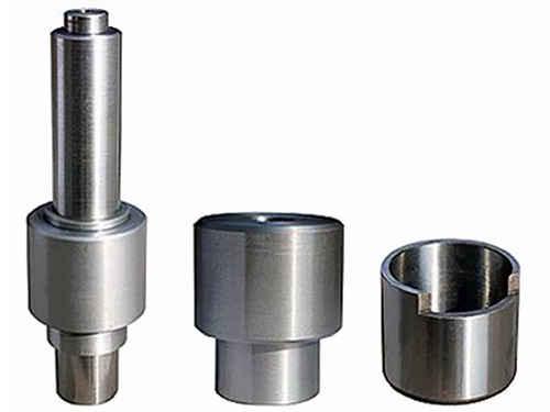
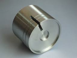
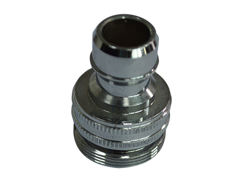
Turning refers to lathe processing, which is part of mechanical processing. Lathe machining mainly uses turning tools to turn workpiece. Lathes are mainly used to machine shafts, discs, sheath and other workpieces with rotating surfaces. They are the most widely used type of machine tooling in machinery manufacturing and repair factories.
Technical brief
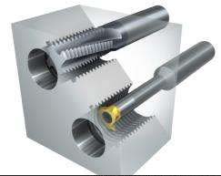
It is on the lathe that the shape and size of the blank are changed by the rotational motion of the workpiece and the linear or curved motion of the tool, and it is processed to meet the requirements of the drawings.
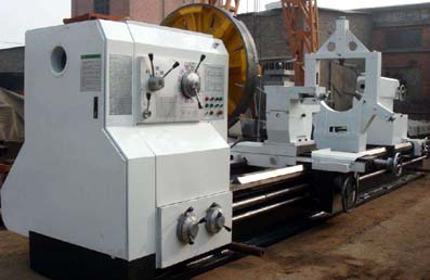
Turning is a method of cutting a workpiece by turning a workpiece relative to a tool on a lathe. The cutting energy of turning is mainly provided by the workpiece instead of the tool. Turning is the most basic and common method of cutting and it occupies a very important position in production. Turning is suitable for machining rotary surfaces. Most workpieces with a rotary surface can be machined by turning. Such as inner and outer cylindrical surfaces, inner and outer conical surfaces, end surfaces, grooves, threads, and rotary forming surfaces, the tools used are mainly turning tools. Lathes are the most widely used category in all types of metal cutting machine tools, accounting for about 50% of the total number of machine tools. The lathe can be used to turn a workpiece with a turning tool, but can also use drills, reamers, taps, and knurling tools for drilling, reaming, tapping, and knurling. According to different characteristics of the process, layout and structural characteristics, lathes can be divided into horizontal lathes, floor-type turning machine, vertical lathes, turret lathes and duplicating lathe, most of which are horizontal lathes.
Technical Problem
Turning machining is the most widely used type in the machine manufacturing industry. The number of lathes is large, the number of people is large, and the processing range is wide. There are many tools and fixtures used, Therefore, the safety and technical issues of turning are especially important. The key tasks are as follows:
1, swarf damage and protective measures.
The steel parts machined on the lathe are more flexible, and the swarf produced during turning is plastic crimped and has sharp edges. In the high-speed cutting of steel parts, red hot spots and long swarfs are formed, which are extremely easy to hurt and often wound around workpieces, turning tools and tool holders. Therefore, the hook should be cleaned or pulled off in a timely manner in the work. If necessary, it should be stopped and cleared. However, it must not be removed or broken by hand. In order to prevent swarf damage, chip breaking, swarf flow control and various protective baffles are often adopted. The chip breaking measure is to grind chip breakers or steps on the turning tool; Use an appropriate chip breaker and mechanically clamp the tool.
2, Workpiece mounting.
In the process of turning, there are many accidents such as damage to the machine tool due to improper installation of the workpiece, breaking or crashing the tool, and falling or flying out of the workpiece.
Therefore, in order to ensure the safe production of turning, special attention must be paid when loading workpieces. For parts of different sizes and shapes, suitable fixtures must be used, regardless of the connection of three-jaw and four-jaw chucks or special fixtures and spindles. Workpieces must be positively clamped and clamped, and large workpieces can be clamped and sleeved.
When the workpiece is rotated at a high speed and the cutting force is applied, it does not shift, fall off, and does not fling. If necessary, it can be reinforced by top center and central frame. Locking, immediately after remove the spanner.
3, Safe Operation.
Before the work, we must fully inspect the machine and confirm that it is in order to use it. The mounting of the workpiece and the tool ensures that the position is correct, firm and reliable. During the machining process, the tool must be stopped when changing the tool, loading and unloading the workpiece, and measuring the workpiece. The workpiece must not be touched by hand or wiped with cotton when rotating. To properly select the cutting speed, feed rate, and Stress depth, no over-load machining is allowed. No workpieces, work clamps, and other debris shall be placed on the tool rest and bed surface. When using a grater, move the turning tool to a safe position with the right hand on the front and the left hand on the back to prevent the sleeves from getting involved. The machine tool must have someone responsible for use and maintenance, and other personnel must not use it.
Precautions
The process of CNC lathe machining is similar to that of ordinary lathes. However, due to the fact that the CNC lathe is installed once and all the turning operations are completed automatically, the following aspects should be noted.
1. Reasonable choice of cutting amount:
For high-efficiency metal cutting, the materials to be machined, cutting tools, and cutting conditions are three major factors. These determine the processing time, tool life and processing quality. The economic and effective processing method must be a reasonable choice of cutting conditions. The three elements of cutting conditions: cutting speed, feed rate, and depth of cut directly cause tool damage. With the increase of cutting speed, the temperature of the tool tip will increase, and it will produce mechanical, chemical and thermal wear. Cutting speed increased by 20%, tool life will be reduced by 1/2. The feed condition and the wear behind the tool are produced within a very small range. However, the feed rate is large, the cutting temperature rises, and the rear wear is large. It has less influence on the tool than the cutting speed. The effect of deep cutting on the cutting tool Although there is no cutting speed and feeding amount, when the cutting depth is small, the material to be cut has a hardened layer, which also affects the service life of the cutting tool. The user selects the cutting speed to be used based on the material to be processed, hardness, cutting condition, material type, feed amount, depth of cut, and the like. The selection of the most suitable processing conditions is selected on the basis of these factors. Regular and stable wear is the ideal condition to achieve life expectancy. However, in actual operation, the choice of tool life is related to the tool wear, the size of the machine being processed, the surface quality, cutting noise, and the processing heat. When determining the processing conditions, it is necessary to conduct research according to actual conditions. For hard-to-machine materials such as stainless steel and heat-resistant alloys, coolants or rigid blades can be used.
2. Reasonable choice of tools:
(1) When roughing, select a tool with high strength and good durability so as to meet the requirements of large depth of cut and large feed amount when roughing.
(2) When finish turning, it is necessary to select tools with high precision and good durability to ensure the processing accuracy.
(3) In order to reduce the tool changing time and facilitate the tool setting, the clamp and blade should be used as far as possible.
3. Reasonably select the fixture:
(1) Try to use a universal fixture to clamp the workpiece to avoid using special fixtures;
(2) Part positioning reference coincides to reduce positioning error.
4. Determine the processing route:
The processing route is the trajectory and direction of the tool relative to the part in the process of index-controlled machine tool machining.
(1) It should be able to ensure processing accuracy and surface roughness requirements;
(2) The processing route should be shortened as much as possible to reduce the tool idle travel time.
5. Processing route and machining allowance:
Under the condition that CNC lathes have not reached universal use, Generally, excessive allowance for blanks, especially the allowance for forging and casting hardcover, should be machined on ordinary lathes. If you must use CNC lathe processing, you need to pay attention to the flexible arrangement of the program.
6. Fixture installation points:
The connection between the hydraulic chuck and the hydraulic clamping cylinder is achieved by the pull rod. The key points of the hydraulic chuck clamping are as follows:
First remove the nut on the hydraulic cylinder with a hand, remove the pull tube, and withdraw the chuck from the rear end of the spindle. Then remove the chuck fixing screw to remove the chuck.
General rules
Turning Processing General Procedures (JB/T9168.2-1998)
Tool setting
1) The tool shank extends out of the tool holder and should not be too long. The general length should not exceed 1.5 times the height of the tool bar (except for the hole, slot, etc.)
2) The center line of lathe tool holder should be perpendicular or parallel to the direction of cutting.
3) Adjustment of the height of the tip of the knife:
(1) When turning a face, turning a conical surface, turning threads, turning a forming surface, and cutting a solid workpiece, the cutting edge should generally be at the same height as the workpiece axis.
(2) The roughing wheel, finishing hole, and tool tip should generally be slightly higher than the workpiece axis.
(3) When the slender shaft, rough hole, and hollow workpiece are cut off, the tool tip should generally be slightly lower than the workpiece axis.
4) The bisector of the thread angle of the thread turning tool should be perpendicular to the workpiece axis.
5) When inserting the turning tool, the washer under the tool bar should be small and flat, and the screw that presses the turning tool should be tightened.
Assembly of workpiece
1) When using a three-jaw self-centering chuck to clamp workpieces for roughing or finishing, If the workpiece diameter is less than 30mm, the overhang length shall not be greater than 5 times the diameter. If the workpiece diameter is greater than 30mm, Its overhang length should not be more than 3 times the diameter.
2) When using a four-jaw, single-action chuck, faceplate, angle iron (bending plate), etc. to clamp irregularly weighted workpieces, weight must be added.
3) When machining a shaft-type workpiece at the tip of the shaft, adjust the tailstock center axis to coincide with the axis of the lathe spindle before turning.
4) When machining slender shafts between the two top centers, a tool holder or a central frame should be used. In the process of processing, attention should be paid to adjusting the top tightness. The top dead center and center frame should pay attention to lubrication.
5) When using the tailstock, the sleeve should be extended as short as possible to reduce vibration.
6)When the vertical lathe is clamped, the supporting surface is small and the workpiece height is high, the heightened claw should be used, and the workpiece should be pressed at the appropriate place with a pull rod or pressing plate.
7) When turning wheels and casting forgings, The unfinished surface should be corrected to ensure uniform wall thickness after processing.
Turning
1) When turning the step shaft, in order to ensure the rigidity during turning, generally the larger diameter part should be turned first, and the smaller diameter part should be turned later.
2) when the shaft have cutting grooves on a workpiece, to be carried out prior to finishing, so as to prevent deformation of the workpiece.
3) When fine turning a threaded shaft,
After threading, the non-threaded part is precision turned.
4) before drilling, the end face of the workpiece should be turned flat. Drill the center hole first if necessary.
5) When drilling deep holes, the pilot hole is generally drilled first.
6) When turning (Φ10-Φ20) mm holes, the diameter of the tool shank should be 0.6-0.7 times the diameter of the machined hole; When the diameter of the hole is greater than that of 20 mm, the knife holder with clamping head should be used.
7) When turning a multi head or multi head screw, After adjusting the exchange gears, make a trial cut.
8) When using the automatic lathe, adjust the relative position of the tool and the workpiece according to the adjustment card of the machine tool. After the adjustment, it is necessary to carry out the trial turning. After the first piece is qualified, it can be processed; During the machining process, the wear of the tool, the workpiece size and the surface roughness are always taken into account.
9) When turning on a vertical lathe, the beam must not be moved freely when the knife holder is adjusted. When turning on the vertical lathe, when the tool rest is adjusted, it is not allowed to move the crossbeam at will.
10) When the relevant surface of the workpiece has positional tolerances, the turning is done in a single clamping as much as possible.
11) When turning a spur gear tooth blank, the hole and reference end face must be machined in one clamping. If necessary, the marking line should be drawn near the end of the gear indexing circle.
 Error compensation
Modern machinery manufacturing technology is moving toward high efficiency, high quality, high precision, high integration, and high intelligence. Precision and ultra-precision machining technology has become the most important component and direction of development in modern machinery manufacturing, and has become a key technology for improving international competitiveness. The turning machining error has become a hot topic of research with the extensive application of precision machining. Since thermal errors and geometric errors account for most of the various errors in the machine tool, the reduction of these two errors, in particular the thermal errors, has become the main goal. Error Compensation Technology (ECT) emerged with the continuous development of science and technology. The losses caused by machine tool thermal deformation are considerable. Therefore, it is extremely necessary to develop a high-precision, low-cost thermal error compensation system that can meet the actual production requirements of the factory to correct thermal errors between the spindle (or workpiece) and the cutting tool. To improve the accuracy of machine tools, reduce waste, increase production efficiency and economic benefits.
Basic definition
The basic definition of error compensation is to artificially create a new error to cancel or greatly reduce the original error that is currently a problem. Through analysis, statistics, induction and mastery of the characteristics and laws of the original error, The error mathematical model was established to try to make the artificially created error equal to the original error and in the opposite direction, thereby reducing the machining error and improving the part dimensional accuracy.
The earliest error compensation was achieved by hardware. Hardware compensation is a mechanical fixed compensation. To change the compensation amount when the machine tool error changes, you must re-create parts, calibration rules, or readjust the compensation mechanism. Hardware compensation also has the disadvantage of not being able to solve random errors and lack of flexibility.
[1] The development of software compensation is characterized by the comprehensive use of advanced technology and computer control technology of various disciplines to improve the accuracy of machine tools without any changes to the machine tool itself. Software compensation overcomes many of the difficulties and disadvantages of hardware compensation and puts compensation technology to a new stage.
Characteristic
Error compensation (technology) has two main features: scientific and engineering.
The rapid development of scientific error compensation technology has greatly enriched the theory of precision mechanical design, precision measurement and the entire precision engineering, and has become an important branch of this discipline. Techniques related to error compensation include detection technology, sensing technology, signal processing technology, photoelectric technology, material technology, computer technology, and control technology. As a new technology branch, error compensation technology has its own independent content and characteristics. Further research on error compensation techniques to make them theoretical and systematic will have very important scientific significance.
The engineering significance of engineering error compensation technology is very significant, it contains three layers of meaning:
First, the use of error compensation technology can easily achieve the level of accuracy that "hard technology" can cost to achieve;
The second is the use of error compensation techniques that can solve the level of accuracy that "hard technology" cannot normally achieve;
Third, if the error compensation technology is adopted under certain accuracy requirements, the cost of instrument and equipment manufacturing can be greatly reduced, which has very significant economic benefits.
Turning machining thermal error generation and classification
With the further improvement of the precision requirements of the machine tool, the proportion of thermal errors in the total error will continue to increase. Machine tool thermal deformation has become a major obstacle to improve the machining accuracy. The thermal error of the machine tool is mainly caused by the thermal deformation of the machine tool components caused by heat sources inside and outside the machine such as motors, bearings, transmission parts, hydraulic systems, ambient temperature, and coolant. The machine tool geometry error comes from the manufacturing defects of the machine tool, the matching error between the machine tool components, the dynamic and static displacement of the machine tool components, and so on.
Basic method of error compensation
In summary and related references, it can be seen that the turning error is generally caused by the following factors:
Machine tool thermal deformation error;
Geometrical errors in machine tool parts and structures;
Cutting force induced error;
Tool wear error;
Other sources of error, such as servo errors in machine tool axes, CNC interpolation algorithm errors, etc.
There are two basic methods for improving machine tool accuracy: error prevention method and error compensation method.
The error prevention method attempts to eliminate or reduce possible sources of error through design and manufacturing approaches. The error prevention method is effective to reduce the temperature rise of the heat source, equalize the temperature field, and reduce the thermal deformation of the machine tool to some extent. However, it is impossible to completely eliminate thermal deformation, and the cost is very expensive; applying thermal error compensation law opens up an effective and economical way to improve the accuracy of machine tools.
Related conclusions
Turning machining error research is the most important component and direction of development in modern machinery manufacturing, and it has become a key technology for improving international competitiveness. The error is produced in many ways. The analysis and research on thermal error is helpful to improve the turning precision and technical requirements.
The error compensation technology can meet the high precision and low cost of the actual production requirements of the factory. Thermal error compensation technology can correct the thermal drift error between the spindle (or workpiece) and the cutting tool, improve the machining accuracy of the machine tool, reduce waste products, increase production efficiency and economic benefits.
common problem
When the ordinary lathe is turning a large pitch thread, sometimes saddle vibration occurs, and the machining surface is corrugated, and the heavy one is fracturing knives.
And when cut, workers often have tie knife or cutting knife phenomenon.
There are many reasons for the above problems. Now we mainly discuss the phenomenon and solutions by analyzing the force conditions of the tools.
1. The cause of the problem and its causes
we know:
When turning a thread with a small pitch, a straight knife cutting method (a straight feed in the direction perpendicular to the workpiece axis) is generally adopted;
When turning a thread with a large pitch, left and right knife cutting methods are often used to reduce the cutting force. (Through moving the small skateboard to make the thread turning tool cut with left and right cutting edges respectively).
When turning the thread, the movement of the saddle is achieved by the rotation of the long screw to drive the movement of the opening and closing nut. There is an axial clearance at the bearing of the long screw, and there is also an axial play between the long screw and the opening nut. When the right main cutting edge of the right-handed worm is strongly machined by the left-right borrow cutting method, The tool is subjected to the force P given to it by the workpiece (ignoring the friction between the chip and the rake face), and the force P is decomposed into an axial component Px and a radial component, where the axial component Px and the feed of the tool In the same direction, the tool passes this axial component Px to the saddle. Thus, the bed saddle is pushed toward the side of the gap to make rapid and swift movements back and forth. As a result, the tool is oscillated back and forth, and the machining surface is corrugated and even broken. However, when cutting with the left main cutting edge, there is no such phenomenon. When cutting with the left main cutting edge, the axial component force Px of the tool is opposite to the feed direction, and the direction of clearance is eliminated. At this time, the saddle moves at a uniform speed. .
When cutting off, the movement of the middle sliding plate is achieved by the rotation of the middle sliding platen screw which drives the nut. There is an axial clearance at the screw shaft bearing and an axial clearance between the screw shaft and the nut. When cutting on a lathe, the rake face of the tool (with the front corner) is subjected to the force P given by the workpiece, (ignoring the friction between the chip and the rake face), Decomposes the force P into force Pz and radial force. The radial component is the same as the cutting direction of the cutting tool. It points to the workpiece and pushes the tool towards the workpiece. This will cause the middle slide to move in the direction of clearance, causing the bending (breaking) of the knife or workpiece.
When cutting off, the movement of the middle sliding plate is achieved by the rotation of the middle sliding platen screw which drives the nut. There is an axial clearance at the screw shaft bearing and an axial clearance between the screw shaft and the nut. When cutting on a lathe, the rake face of the tool (with the front corner) is subjected to the force P given by the workpiece, (ignoring the friction between the chip and the rake face), Decomposes the force P into force Pz and radial force. The radial component is the same as the cutting direction of the cutting tool. It points to the workpiece and pushes the tool towards the workpiece. This will cause the middle slide to move in the direction of clearance, causing the bending (breaking) of the knife or workpiece.
2. Solution
When the turning pitch is larger and the thread of the left and right borrow cutting method is used, in addition to adjusting the relevant parameters of the lathe, the clearance between the saddle and the bed rail should be adjusted to make it slightly tighter. In order to increase the friction during movement, the possibility of turbulence in the saddle is reduced, but this gap cannot be adjusted too tightly so that it is appropriate to shake the saddle steadily.
Adjust the clearance of the middle skateboard to minimize the gap; Adjust the tightness of the small skateboard to make it slightly tighter to prevent the turning of the turning tool when turning. The length of the workpiece and the tool bar should be shortened as much as possible, and the left main blade should be used as far as possible; When cutting with the right main blade, it is necessary to reduce the amount of back knife; Increase the rake angle of the right main cutting edge. The edge of the cutting edge should be straight and sharp to reduce the axial component force Px of the tool. In theory, the larger the rake angle of the right main blade, the better.
Turning refers to lathe processing, which is part of mechanical processing. Lathe machining mainly uses turning tools to turn workpiece. Lathes are mainly used to machine shafts, discs, sheath and other workpieces with rotating surfaces. They are the most widely used type of machine tooling in machinery manufacturing and repair factories.
Technical brief
It is on the lathe that the shape and size of the blank are changed by the rotational motion of the workpiece and the linear or curved motion of the tool, and it is processed to meet the requirements of the drawings.
Turning is a method of cutting a workpiece by turning a workpiece relative to a tool on a lathe. The cutting energy of turning is mainly provided by the workpiece instead of the tool. Turning is the most basic and common method of cutting and it occupies a very important position in production. Turning is suitable for machining rotary surfaces. Most workpieces with a rotary surface can be machined by turning. Such as inner and outer cylindrical surfaces, inner and outer conical surfaces, end surfaces, grooves, threads, and rotary forming surfaces, the tools used are mainly turning tools. Lathes are the most widely used category in all types of metal cutting machine tools, accounting for about 50% of the total number of machine tools. The lathe can be used to turn a workpiece with a turning tool, but can also use drills, reamers, taps, and knurling tools for drilling, reaming, tapping, and knurling. According to different characteristics of the process, layout and structural characteristics, lathes can be divided into horizontal lathes, floor-type turning machine, vertical lathes, turret lathes and duplicating lathe, most of which are horizontal lathes.
Technical Problem
Turning machining is the most widely used type in the machine manufacturing industry. The number of lathes is large, the number of people is large, and the processing range is wide. There are many tools and fixtures used, Therefore, the safety and technical issues of turning are especially important. The key tasks are as follows:
1, swarf damage and protective measures.
The steel parts machined on the lathe are more flexible, and the swarf produced during turning is plastic crimped and has sharp edges. In the high-speed cutting of steel parts, red hot spots and long swarfs are formed, which are extremely easy to hurt and often wound around workpieces, turning tools and tool holders. Therefore, the hook should be cleaned or pulled off in a timely manner in the work. If necessary, it should be stopped and cleared. However, it must not be removed or broken by hand. In order to prevent swarf damage, chip breaking, swarf flow control and various protective baffles are often adopted. The chip breaking measure is to grind chip breakers or steps on the turning tool; Use an appropriate chip breaker and mechanically clamp the tool.
2, Workpiece mounting.
In the process of turning, there are many accidents such as damage to the machine tool due to improper installation of the workpiece, breaking or crashing the tool, and falling or flying out of the workpiece.
Therefore, in order to ensure the safe production of turning, special attention must be paid when loading workpieces. For parts of different sizes and shapes, suitable fixtures must be used, regardless of the connection of three-jaw and four-jaw chucks or special fixtures and spindles. Workpieces must be positively clamped and clamped, and large workpieces can be clamped and sleeved.
When the workpiece is rotated at a high speed and the cutting force is applied, it does not shift, fall off, and does not fling. If necessary, it can be reinforced by top center and central frame. Locking, immediately after remove the spanner.
3, Safe Operation.
Before the work, we must fully inspect the machine and confirm that it is in order to use it. The mounting of the workpiece and the tool ensures that the position is correct, firm and reliable. During the machining process, the tool must be stopped when changing the tool, loading and unloading the workpiece, and measuring the workpiece. The workpiece must not be touched by hand or wiped with cotton when rotating. To properly select the cutting speed, feed rate, and Stress depth, no over-load machining is allowed. No workpieces, work clamps, and other debris shall be placed on the tool rest and bed surface. When using a grater, move the turning tool to a safe position with the right hand on the front and the left hand on the back to prevent the sleeves from getting involved. The machine tool must have someone responsible for use and maintenance, and other personnel must not use it.
Precautions
The process of CNC lathe machining is similar to that of ordinary lathes. However, due to the fact that the CNC lathe is installed once and all the turning operations are completed automatically, the following aspects should be noted.
1. Reasonable choice of cutting amount:
For high-efficiency metal cutting, the materials to be machined, cutting tools, and cutting conditions are three major factors. These determine the processing time, tool life and processing quality. The economic and effective processing method must be a reasonable choice of cutting conditions. The three elements of cutting conditions: cutting speed, feed rate, and depth of cut directly cause tool damage. With the increase of cutting speed, the temperature of the tool tip will increase, and it will produce mechanical, chemical and thermal wear. Cutting speed increased by 20%, tool life will be reduced by 1/2. The feed condition and the wear behind the tool are produced within a very small range. However, the feed rate is large, the cutting temperature rises, and the rear wear is large. It has less influence on the tool than the cutting speed. The effect of deep cutting on the cutting tool Although there is no cutting speed and feeding amount, when the cutting depth is small, the material to be cut has a hardened layer, which also affects the service life of the cutting tool. The user selects the cutting speed to be used based on the material to be processed, hardness, cutting condition, material type, feed amount, depth of cut, and the like. The selection of the most suitable processing conditions is selected on the basis of these factors. Regular and stable wear is the ideal condition to achieve life expectancy. However, in actual operation, the choice of tool life is related to the tool wear, the size of the machine being processed, the surface quality, cutting noise, and the processing heat. When determining the processing conditions, it is necessary to conduct research according to actual conditions. For hard-to-machine materials such as stainless steel and heat-resistant alloys, coolants or rigid blades can be used.
2. Reasonable choice of tools:
(1) When roughing, select a tool with high strength and good durability so as to meet the requirements of large depth of cut and large feed amount when roughing.
(2) When finish turning, it is necessary to select tools with high precision and good durability to ensure the processing accuracy.
(3) In order to reduce the tool changing time and facilitate the tool setting, the clamp and blade should be used as far as possible.
3. Reasonably select the fixture:
(1) Try to use a universal fixture to clamp the workpiece to avoid using special fixtures;
(2) Part positioning reference coincides to reduce positioning error.
4. Determine the processing route:
The processing route is the trajectory and direction of the tool relative to the part in the process of index-controlled machine tool machining.
(1) It should be able to ensure processing accuracy and surface roughness requirements;
(2) The processing route should be shortened as much as possible to reduce the tool idle travel time.
5. Processing route and machining allowance:
Under the condition that CNC lathes have not reached universal use, Generally, excessive allowance for blanks, especially the allowance for forging and casting hardcover, should be machined on ordinary lathes. If you must use CNC lathe processing, you need to pay attention to the flexible arrangement of the program.
6. Fixture installation points:
The connection between the hydraulic chuck and the hydraulic clamping cylinder is achieved by the pull rod. The key points of the hydraulic chuck clamping are as follows:
First remove the nut on the hydraulic cylinder with a hand, remove the pull tube, and withdraw the chuck from the rear end of the spindle. Then remove the chuck fixing screw to remove the chuck.
General rules
Turning Processing General Procedures (JB/T9168.2-1998)
Tool setting
1) The tool shank extends out of the tool holder and should not be too long. The general length should not exceed 1.5 times the height of the tool bar (except for the hole, slot, etc.)
2) The center line of lathe tool holder should be perpendicular or parallel to the direction of cutting.
3) Adjustment of the height of the tip of the knife:
(1) When turning a face, turning a conical surface, turning threads, turning a forming surface, and cutting a solid workpiece, the cutting edge should generally be at the same height as the workpiece axis.
(2) The roughing wheel, finishing hole, and tool tip should generally be slightly higher than the workpiece axis.
(3) When the slender shaft, rough hole, and hollow workpiece are cut off, the tool tip should generally be slightly lower than the workpiece axis.
4) The bisector of the thread angle of the thread turning tool should be perpendicular to the workpiece axis.
5) When inserting the turning tool, the washer under the tool bar should be small and flat, and the screw that presses the turning tool should be tightened.
Assembly of workpiece
1) When using a three-jaw self-centering chuck to clamp workpieces for roughing or finishing, If the workpiece diameter is less than 30mm, the overhang length shall not be greater than 5 times the diameter. If the workpiece diameter is greater than 30mm, Its overhang length should not be more than 3 times the diameter.
2) When using a four-jaw, single-action chuck, faceplate, angle iron (bending plate), etc. to clamp irregularly weighted workpieces, weight must be added.
3) When machining a shaft-type workpiece at the tip of the shaft, adjust the tailstock center axis to coincide with the axis of the lathe spindle before turning.
4) When machining slender shafts between the two top centers, a tool holder or a central frame should be used. In the process of processing, attention should be paid to adjusting the top tightness. The top dead center and center frame should pay attention to lubrication.
5) When using the tailstock, the sleeve should be extended as short as possible to reduce vibration.
6)When the vertical lathe is clamped, the supporting surface is small and the workpiece height is high, the heightened claw should be used, and the workpiece should be pressed at the appropriate place with a pull rod or pressing plate.
7) When turning wheels and casting forgings, The unfinished surface should be corrected to ensure uniform wall thickness after processing.
Turning
1) When turning the step shaft, in order to ensure the rigidity during turning, generally the larger diameter part should be turned first, and the smaller diameter part should be turned later.
2) when the shaft have cutting grooves on a workpiece, to be carried out prior to finishing, so as to prevent deformation of the workpiece.
3) When fine turning a threaded shaft,
After threading, the non-threaded part is precision turned.
4) before drilling, the end face of the workpiece should be turned flat. Drill the center hole first if necessary.
5) When drilling deep holes, the pilot hole is generally drilled first.
6) When turning (Φ10-Φ20) mm holes, the diameter of the tool shank should be 0.6-0.7 times the diameter of the machined hole; When the diameter of the hole is greater than that of 20 mm, the knife holder with clamping head should be used.
7) When turning a multi head or multi head screw, After adjusting the exchange gears, make a trial cut.
8) When using the automatic lathe, adjust the relative position of the tool and the workpiece according to the adjustment card of the machine tool. After the adjustment, it is necessary to carry out the trial turning. After the first piece is qualified, it can be processed; During the machining process, the wear of the tool, the workpiece size and the surface roughness are always taken into account.
9) When turning on a vertical lathe, the beam must not be moved freely when the knife holder is adjusted. When turning on the vertical lathe, when the tool rest is adjusted, it is not allowed to move the crossbeam at will.
10) When the relevant surface of the workpiece has positional tolerances, the turning is done in a single clamping as much as possible.
11) When turning a spur gear tooth blank, the hole and reference end face must be machined in one clamping. If necessary, the marking line should be drawn near the end of the gear indexing circle.
Modern machinery manufacturing technology is moving toward high efficiency, high quality, high precision, high integration, and high intelligence. Precision and ultra-precision machining technology has become the most important component and direction of development in modern machinery manufacturing, and has become a key technology for improving international competitiveness. The turning machining error has become a hot topic of research with the extensive application of precision machining. Since thermal errors and geometric errors account for most of the various errors in the machine tool, the reduction of these two errors, in particular the thermal errors, has become the main goal. Error Compensation Technology (ECT) emerged with the continuous development of science and technology. The losses caused by machine tool thermal deformation are considerable. Therefore, it is extremely necessary to develop a high-precision, low-cost thermal error compensation system that can meet the actual production requirements of the factory to correct thermal errors between the spindle (or workpiece) and the cutting tool. To improve the accuracy of machine tools, reduce waste, increase production efficiency and economic benefits.
Basic definition
The basic definition of error compensation is to artificially create a new error to cancel or greatly reduce the original error that is currently a problem. Through analysis, statistics, induction and mastery of the characteristics and laws of the original error, The error mathematical model was established to try to make the artificially created error equal to the original error and in the opposite direction, thereby reducing the machining error and improving the part dimensional accuracy.
The earliest error compensation was achieved by hardware. Hardware compensation is a mechanical fixed compensation. To change the compensation amount when the machine tool error changes, you must re-create parts, calibration rules, or readjust the compensation mechanism. Hardware compensation also has the disadvantage of not being able to solve random errors and lack of flexibility.
[1] The development of software compensation is characterized by the comprehensive use of advanced technology and computer control technology of various disciplines to improve the accuracy of machine tools without any changes to the machine tool itself. Software compensation overcomes many of the difficulties and disadvantages of hardware compensation and puts compensation technology to a new stage.
Characteristic
Error compensation (technology) has two main features: scientific and engineering.
The rapid development of scientific error compensation technology has greatly enriched the theory of precision mechanical design, precision measurement and the entire precision engineering, and has become an important branch of this discipline. Techniques related to error compensation include detection technology, sensing technology, signal processing technology, photoelectric technology, material technology, computer technology, and control technology. As a new technology branch, error compensation technology has its own independent content and characteristics. Further research on error compensation techniques to make them theoretical and systematic will have very important scientific significance.
The engineering significance of engineering error compensation technology is very significant, it contains three layers of meaning:
First, the use of error compensation technology can easily achieve the level of accuracy that "hard technology" can cost to achieve;
The second is the use of error compensation techniques that can solve the level of accuracy that "hard technology" cannot normally achieve;
Third, if the error compensation technology is adopted under certain accuracy requirements, the cost of instrument and equipment manufacturing can be greatly reduced, which has very significant economic benefits.
Turning machining thermal error generation and classification
With the further improvement of the precision requirements of the machine tool, the proportion of thermal errors in the total error will continue to increase. Machine tool thermal deformation has become a major obstacle to improve the machining accuracy. The thermal error of the machine tool is mainly caused by the thermal deformation of the machine tool components caused by heat sources inside and outside the machine such as motors, bearings, transmission parts, hydraulic systems, ambient temperature, and coolant. The machine tool geometry error comes from the manufacturing defects of the machine tool, the matching error between the machine tool components, the dynamic and static displacement of the machine tool components, and so on.
Basic method of error compensation
In summary and related references, it can be seen that the turning error is generally caused by the following factors:
Machine tool thermal deformation error;
Geometrical errors in machine tool parts and structures;
Cutting force induced error;
Tool wear error;
Other sources of error, such as servo errors in machine tool axes, CNC interpolation algorithm errors, etc.
There are two basic methods for improving machine tool accuracy: error prevention method and error compensation method.
The error prevention method attempts to eliminate or reduce possible sources of error through design and manufacturing approaches. The error prevention method is effective to reduce the temperature rise of the heat source, equalize the temperature field, and reduce the thermal deformation of the machine tool to some extent. However, it is impossible to completely eliminate thermal deformation, and the cost is very expensive; applying thermal error compensation law opens up an effective and economical way to improve the accuracy of machine tools.
Related conclusions
Turning machining error research is the most important component and direction of development in modern machinery manufacturing, and it has become a key technology for improving international competitiveness. The error is produced in many ways. The analysis and research on thermal error is helpful to improve the turning precision and technical requirements.
The error compensation technology can meet the high precision and low cost of the actual production requirements of the factory. Thermal error compensation technology can correct the thermal drift error between the spindle (or workpiece) and the cutting tool, improve the machining accuracy of the machine tool, reduce waste products, increase production efficiency and economic benefits.
common problem
When the ordinary lathe is turning a large pitch thread, sometimes saddle vibration occurs, and the machining surface is corrugated, and the heavy one is fracturing knives.
And when cut, workers often have tie knife or cutting knife phenomenon.
There are many reasons for the above problems. Now we mainly discuss the phenomenon and solutions by analyzing the force conditions of the tools.
1. The cause of the problem and its causes
we know:
When turning a thread with a small pitch, a straight knife cutting method (a straight feed in the direction perpendicular to the workpiece axis) is generally adopted;
When turning a thread with a large pitch, left and right knife cutting methods are often used to reduce the cutting force. (Through moving the small skateboard to make the thread turning tool cut with left and right cutting edges respectively).
When turning the thread, the movement of the saddle is achieved by the rotation of the long screw to drive the movement of the opening and closing nut. There is an axial clearance at the bearing of the long screw, and there is also an axial play between the long screw and the opening nut. When the right main cutting edge of the right-handed worm is strongly machined by the left-right borrow cutting method, The tool is subjected to the force P given to it by the workpiece (ignoring the friction between the chip and the rake face), and the force P is decomposed into an axial component Px and a radial component, where the axial component Px and the feed of the tool In the same direction, the tool passes this axial component Px to the saddle. Thus, the bed saddle is pushed toward the side of the gap to make rapid and swift movements back and forth. As a result, the tool is oscillated back and forth, and the machining surface is corrugated and even broken. However, when cutting with the left main cutting edge, there is no such phenomenon. When cutting with the left main cutting edge, the axial component force Px of the tool is opposite to the feed direction, and the direction of clearance is eliminated. At this time, the saddle moves at a uniform speed. .
When cutting off, the movement of the middle sliding plate is achieved by the rotation of the middle sliding platen screw which drives the nut. There is an axial clearance at the screw shaft bearing and an axial clearance between the screw shaft and the nut. When cutting on a lathe, the rake face of the tool (with the front corner) is subjected to the force P given by the workpiece, (ignoring the friction between the chip and the rake face), Decomposes the force P into force Pz and radial force. The radial component is the same as the cutting direction of the cutting tool. It points to the workpiece and pushes the tool towards the workpiece. This will cause the middle slide to move in the direction of clearance, causing the bending (breaking) of the knife or workpiece.
When cutting off, the movement of the middle sliding plate is achieved by the rotation of the middle sliding platen screw which drives the nut. There is an axial clearance at the screw shaft bearing and an axial clearance between the screw shaft and the nut. When cutting on a lathe, the rake face of the tool (with the front corner) is subjected to the force P given by the workpiece, (ignoring the friction between the chip and the rake face), Decomposes the force P into force Pz and radial force. The radial component is the same as the cutting direction of the cutting tool. It points to the workpiece and pushes the tool towards the workpiece. This will cause the middle slide to move in the direction of clearance, causing the bending (breaking) of the knife or workpiece.
2. Solution
When the turning pitch is larger and the thread of the left and right borrow cutting method is used, in addition to adjusting the relevant parameters of the lathe, the clearance between the saddle and the bed rail should be adjusted to make it slightly tighter. In order to increase the friction during movement, the possibility of turbulence in the saddle is reduced, but this gap cannot be adjusted too tightly so that it is appropriate to shake the saddle steadily.
Adjust the clearance of the middle skateboard to minimize the gap; Adjust the tightness of the small skateboard to make it slightly tighter to prevent the turning of the turning tool when turning. The length of the workpiece and the tool bar should be shortened as much as possible, and the left main blade should be used as far as possible; When cutting with the right main blade, it is necessary to reduce the amount of back knife; Increase the rake angle of the right main cutting edge. The edge of the cutting edge should be straight and sharp to reduce the axial component force Px of the tool. In theory, the larger the rake angle of the right main blade, the better.


