The Method Of Turning An Elongate Shaft
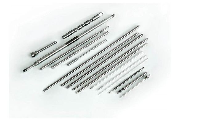
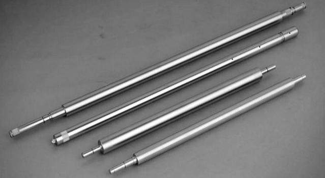
1.Turning slender shaft geometry accuracy and surface quality requirements are high. Conventional processing methods are used to clamp the workpiece between the main shaft and the tailstock. There is no flexibility at both ends. Under the influence of cutting force and thermal expansion, the workpiece generates internal stress and bending deformation, and it is difficult to ensure straightness and dimensional accuracy. The reverse direction method is a method to overcome the above phenomenon. It is suitable for medium speed roughing and large cutting low speed finishing, and has the characteristics of strong adaptability, low precision of machine tool and high processing efficiency.
3. Process characteristics:
(1) Change the way of conventional machining methods to clamp the workpiece, change the surface contact to line contact, and reduce the stress deformation.
(2) The tip of the tail is changed to a flexible spring tip, which eliminates the forced bending of the workpiece due to thermal elongation.
(3) The use of the three-jaw tool holder can better ensure the parallel movement of the centripetal center and prevent the chattering of the slender shaft during turning. (Note: loosen the tool holder before machining, then drive to eat the knife. Quickly follow the knife holder, do not retract the knife when contacting the tool holder, and adjust the strength of the blade bracket claw and the shaft surface so as not to deform the shaft top to fit too loose or too tight. The contact between the blade holder claw and the surface of the shaft should be tight, and the shaft and the claw should be lubricated, so that the cutting can be prevented, and the slender shaft can be prevented from forming a bamboo shape. )
(4) The cutting is performed from the front end to the tailstock direction, and the axial cutting force straightens the cut portion of the workpiece and advances the portion to be processed of the workpiece to move toward the tailstock.
Tool selection and use
Since the rigidity of the elongated shaft is insufficient, the radial cutting force is required to be as small as possible. Therefore, the cutting edge of the tool is required to be sharp, the cutting is light, the chip removal is smooth, and the durability is high. The principle is to increase the rake angle and lead angle as much as possible without affecting the strength of the tool. Common main deflection angle φ = 75 ° ~ 90 °, the rake angle γ = 28 ° ~ 30 °. The carbide insert is yT15 and the shank is 45 high quality carbon steel. Main deflection angle φ = 75 °. The main cutting edge has a rake angle of γ=25°, a rib front angle of 25°, and a chamfering of 0.4 to 0.8 mm. Due to the action of chamfering and R4mm chipbreaker, it has good chip breaking performance. At the same time, due to the increase of the tool nose angle, the tool tip strength and heat dissipation conditions are increased. The main back angle of the turning tool is α=8°, the chamfering edge is 0.1-0.3mm, and the rear corner angle is -12°. This increases the contact area of the backing surface of the turning tool to support the workpiece and prevents the internal structure of the workpiece material. Non-uniform sickle phenomenon and eliminate low frequency vibration.
1, Finishing turning knife.
The tool structure adopts elastic shank to reduce vibration and improve cutting conditions. The cemented carbide insert adopts YT15, and the cutter tip should be made 0.1mm lower than the center of the shaft. The blade is wider and the wiper blade is 8 to 10 mm.
The utility model can maintain a certain contact area between the turning tool and the shaft member, and the cutting edge is turned on the shaft member to prevent the sickle from being criticized when the turning force changes. The main declination is small to form a thin and small deformation, which is beneficial to improve the surface finish of the machined surface, and the rake angle is γ=30°, which makes the cutting light.
Choose a reasonable amount of cutting
In the reverse turning of the slender shaft, there are special requirements for the amount of cutting. It requires taking the maximum feed rate F, in order to increase the axial tensile stress in the workpiece, substantially to prevent vibration of the workpiece. However, the choice of cutting amount is limited by the geometry error of the machined surface. The order of selection is usually: first take the maximum feed amount, then take the maximum amount of knife ap, and finally take the maximum cutting speed v. Practice has proved that when the ratio of the length to the diameter of the workpiece is 40 to 120, if v = 40 m / min, f is preferably taken from 0.35 to 0.5 mm / r; If v = 45 ~ 100m / min, f should be 0.6 ~ 1.2mm / r is appropriate. In the actual operation, the cutting amount is selected: When roughing, the cutting speed is 50-60 m/min, the feed rate is 0.3-0.4 mm/r, and the cutting depth is 1.5-2 mm; When the is Fine turning, the cutting speed is 60 to 100 m/min, the feed rate is 0.08 to 0.12 mm/r, and the cutting depth is 0.5 to 1 mm.
In the reverse turning of the slender shaft, there are special requirements for the amount of cutting. It requires taking the maximum feed rate F, in order to increase the axial tensile stress in the workpiece, substantially to prevent vibration of the workpiece. However, the choice of cutting amount is limited by the geometry error of the machined surface. The order of selection is usually: first take the maximum feed amount, then take the maximum amount of knife ap, and finally take the maximum cutting speed v. Practice has proved that when the ratio of the length to the diameter of the workpiece is 40 to 120, if v = 40 m / min, f is preferably taken from 0.35 to 0.5 mm / r; If v = 45 ~ 100m / min, f should be 0.6 ~ 1.2mm / r is appropriate. In the actual operation, the cutting amount is selected: When roughing, the cutting speed is 50-60 m/min, the feed rate is 0.3-0.4 mm/r, and the cutting depth is 1.5-2 mm; When the is Fine turning, the cutting speed is 60 to 100 m/min, the feed rate is 0.08 to 0.12 mm/r, and the cutting depth is 0.5 to 1 mm.