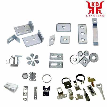
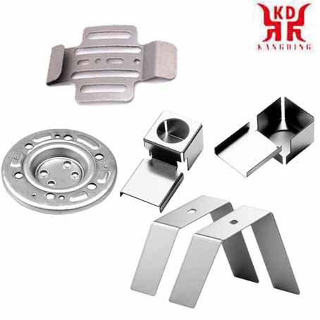
Stamping Parts Forming Technology
The forming technology of stamping die and the forming process design of stamping parts
Digital coding sheet
With the rapid economic development and the diversification of market demand, people have shorter and shorter requirements for product production cycles, especially in small batches or even single-piece production. Modern manufacturing technology is required not only to have higher flexibility, but also to have a newer production model that can better meet the rapidly changing market requirements. The rapid prototyping technology of CNC unit stamping dies is produced to adapt to this situation.
The shape of the sheet metal parts can be divided into some simple graphic elements, and then combined into the required graphics. For example: A rectangle is a composite of 4 right angles; a wave shape is a composite of some curves, etc. Therefore, for some sheet metal parts that require high precision in small batches or even single-piece production, some general-purpose parts can be quickly assembled into unit stamping dies, and numerical control technology can be used to make them quickly shaped. The processed sheet metal part is regarded as a plane figure that can be divided, and the simple figure elements that are separated out are digitally processed. That is, the positioning code is performed according to its position. As shown in Figure 1: In the digitization of non-equidistant simple graphic parts, the (Δx, Δy) of the gaps 1, 2, 3, 4 are all equal, and the (Δx, Δy) of the square hole 5 is equal to twice the (Δx, Δy) ). Assuming that the width of the existing general-purpose punch is equal to Δx and the length is equal to Δy, then the numbers are numbered as shown in Figure 1. Gap 1 is composed of position (2,0) and position (3,0), gaps 2, 3, and 4 are also composed of two positions, and square holes are composed of 8 positions. If a rectangular unit is used for rapid prototyping, a two-dimensional code as shown in the upper figure of Figure 2 can be obtained, and the resulting code is longer due to too fine division. If the square unit is used for rapid prototyping, the two-dimensional code as shown in the figure below can be obtained, and the code is reduced by half.
The two-dimensional coding of the rectangular unit is as follows:
For equidistant simple graphic parts: For rapid prototyping of the tooth profile of a key, the coding can be further simplified due to the equal tooth pitch. A schematic diagram of the key's tooth profile coding, as shown in Figure 3. In Fig. 3, triangular units are used, and the trapezoidal unit coding can be reduced to a one-dimensional array in practical applications.
Parameter definition:
Number of teeth - the number of CNC stampings, now it is 5.
Tooth pitch - the distance of each movement in the Y direction when CNC punching.
Step difference value — the distance when CNC punching, when moving one unit in the X direction.
Number of steps - the movement unit in the X direction when CNC punching.
When the pitch and level difference value are selected, the key's tooth profile processing position can be converted into a level difference number, and finally the tooth profile code is a one-dimensional array (2 1 3 2 1).
It can be seen from the above that digital coding is the key to rapid prototyping of unit die. Appropriate coding can not only improve production efficiency, but also save storage memory.
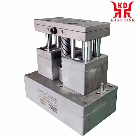
Structural design
Most small and medium-sized enterprises do not yet have the financial strength to purchase high-end CNC punching machines. The stamping die of the numerical control unit can be directly installed on an ordinary punching machine and used as a simple numerical control punching machine.The schematic diagram of the rapid prototyping mold mechanism is shown in Figure 4. The upper mold is a punch mechanism. The photoelectric head is installed under the upper template to detect the rise and fall of the punch. The clamping of the blank should be designed according to different needs. The material plate is driven in X and Y directions by the stepper motor control screw. The lower mold is a concave mold mechanism, which is directly installed on the workbench.
system design
1. Motor drive and selectionStepping motor is an actuator that converts electrical pulses into angular displacement. There are 3 types: permanent magnet type, reactive type and hybrid type. The hybrid combines the advantages of the first two. Considering comprehensively from the aspect of cost performance, it is proposed to choose a two-phase hybrid stepping motor with a step angle of 1.80.
There are many types and types of drives, and the subdivision type is considered. Because the subdivision type can eliminate the low frequency oscillation of the motor, it can improve the output torque and resolution of the motor. Taking into account the speed and accuracy of the subdivision coefficient is set to 4.
2. System hardware design
The stamping die of the CNC unit is installed on the crankshaft press, and the stamping principle of the machine tool remains unchanged. What needs to be controlled is two aspects: First, determine the position of the zero point and each station point; Secondly, between the start and stop of the reciprocating action of the upper stamping die, the fast feed movement of the workpiece in the X and Y directions obtained by coding and the coordination of these two actions. That is to realize the synchronous control of stamping and feeding actions. Control system block diagram, as shown in Figure 5. Photoelectric signal detection circuit diagram, as shown in Figure 6.
The man-machine interface of the numerical control system adopts keyboard input. The LED display keyboard has function keys for number keys, setting, modification, search, adjustment in X and Y directions, and execution. It can be used to complete the input and modification of the processing program and the operation and adjustment of the control. The operator encodes on the computer according to the shape of the workpiece to automatically generate the processing program, and downloads the processing program to the single-chip microcomputer through the serial port and saves it in the FLASH ROM. Manually adjust the zero position after the mold is installed. After entering the execution, the MCU obtains the processing program from the FLASH ROM. After calculating the step distance in the X and Y directions, it is converted into the corresponding step pulse number to control the number of rotation steps of the stepping motor in the X and Y directions. When the photoelectric signal detects that the upper mold is in the open position, the numerical control system quickly positions the workpiece to be processed to the processing position, and starts the pressing of the punch on the punch to realize a CNC punching. When the punch drives the upper die to open, the numerical control system quickly moves the workpiece to be processed to the next processing position to wait for the next punching, and stops the punch movement until the processing is completed.
3. System software design
The entire system is managed by the host computer. The system software language adopts Visual Basic 6.0 to compile its integrated development environment (IDE) integrating design, modification, debugging, generation and other functions, and the human-computer interaction interface is very friendly. It is a powerful programming language in the Windows environment that is easy to learn and has a high degree of visualization.
The system software structure adopts a modular structure, with 5 functional modules in total:
After the system is turned on, enter the Windows interface and double-click the "Numerical Control Unit Die" icon, then the application interface will pop up and you can select functional modules. The system software function module diagram is shown as in Fig. 7.
The editing module is used to complete the editing, modification, and generation of the program for the user to operate the set parameter group.
The parameter setting module makes the input parameter group into a data table, and sends it to the database for the call of the program.
The operation management module is responsible for the operation and interruption of the program.
The communication module is responsible for the communication management between the upper and lower computers, which is to use the MSCOMM control for the control program segment and the parameter group called. It is sent to the single-chip microcomputer through the RS232 serial port to make the single-chip microcomputer perform control work.
Query module. It is convenient for users to view and call the saved files.
The program of the one-chip computer also adopts the modular structure, and there are 5 functional modules in total like the upper computer. Through the communication interface, it accepts the input instructions from the host computer to control the movement of the stepper motor in the X and Y directions. It can also be separated from the host computer to directly control the operation. The upper computer communication program flow chart, as shown in the left picture of Fig. 8. The flow chart of the communication program of the lower computer is shown in the right figure of Fig. 8.
With the development of numerical control technology, servo technology, moving components, and the needs of market economy, the rapid prototyping technology of CNC unit stamping die has been developed rapidly. For small and medium-sized traditional enterprises, this high-tech combined with traditional manufacturing technology is undoubtedly a kind of investment province, effective and convenient technology. With the continuous development of economy and science and technology, the realization of automatic loading and unloading equipment and external mold library automatic mold changing equipment have been placed in front of people. It can be seen that the development of CNC stamping is based on the development of related technologies and new structures. The rapid prototyping technology of unit stamping die is undoubtedly a new starting point for the development of advanced CNC stamping technology.


