CNC Stamping Parts Supplier
What are stamping parts? Design and forming process of stamping parts
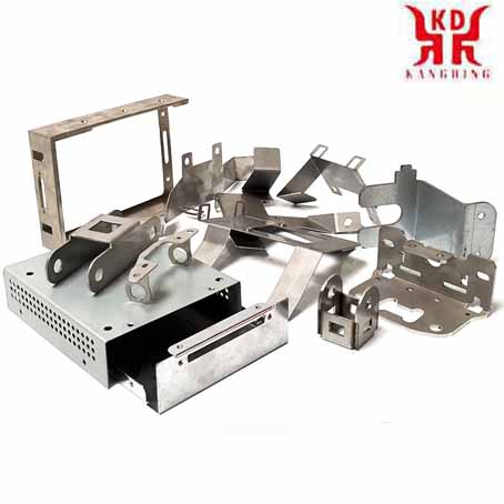
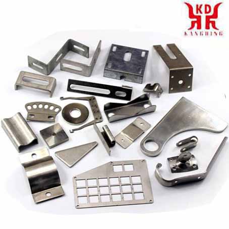
Stamping parts are processing methods that rely on presses and dies to apply punching pressure to plates, strips, pipes and profiles to produce plastic deformation or separate forming, so as to obtain workpieces (stamping parts) of the required shape and size. Stamping and forging are both plastic processing (or pressure processing), collectively known as forging. The blanks to be stamped are mainly hot-rolled and cold-rolled steel plates and strips.

Introduction
In steel, 60 to 70% are plates, most of which are stamped into finished parts. The car body, chassis, fuel tank, radiator fins, boiler drums, container shells, motors, electrical iron core silicon steel sheets, etc. are all stamped and processed. There are also a large number of stamping parts in products such as instruments, household appliances, bicycles, office machinery, and living utensils.Compared with castings and forgings, stamping parts have the characteristics of thinness, uniformity, lightness and strong rigidity. Stamping can produce workpieces with stiffeners, ribs, undulations or flanges that are difficult to manufacture by other methods to improve their rigidity. Due to the use of precision molds, the accuracy of the workpiece can reach the micron level, and the repeatability is high, the specifications are consistent, and holes, bosses, etc. can be punched out.
Cold stamping parts are generally no longer processed by CNC machining, or only a small amount of machining is required. The precision and surface condition of hot stamping parts are lower than cold stamping parts, but still better than castings and forgings, and the cutting amount is less.
Stamping is an efficient production method. Compound stamping dies, especially continuous stamping dies, can be used to complete multiple stamping processes on a single press to realize fully automatic production from strip uncoiling, leveling, punching to forming and finishing. The production efficiency is high, the working conditions are good, and the production cost is low. Generally hundreds of pieces can be produced per minute.
Stamping parts are mainly classified by process, which can be divided into two categories: separation process and forming process. The separation process is also called punching, and its purpose is to separate the stamping parts from the sheet along a certain contour line while ensuring the quality requirements of the separated section. The surface and internal properties of the stamping sheet material have a great influence on the quality of the stamped product, and the thickness of the stamping material is required to be accurate and uniform; The surface is smooth, no spots, no scars, no scratches, no surface cracks, etc.; The yield strength is uniform without obvious directionality; the uniform elongation is high; Low flex-strength ratio; Work hardening is low.

main feature
Stamping parts are mainly formed by stamping metal or non-metal sheet materials with the pressure of a press through a stamping die. It mainly has the following characteristics:⑴ Stamping parts are manufactured by stamping under the premise of low material consumption. The parts are light in weight and rigid, and after the sheet metal is plastically deformed, the internal structure of the metal is improved, which improves the strength of the stamping parts.
⑵ The stamping parts have high dimensional accuracy, the same size as the mold parts, and good interchangeability. No further machining is required to meet general assembly and use requirements.
⑶ In the stamping process, since the surface of the material is not damaged, the stamping parts have a good surface quality and a smooth and beautiful appearance. This provides convenient conditions for surface painting, electroplating, phosphating and other surface treatments.
Design principles of stamping parts
⑴ The designed stamping parts must meet the product use and technical performance, and be easy to assemble and repair.⑵ The designed stamping parts must be conducive to improving the utilization rate of metal materials, reducing material varieties and specifications, and reducing material consumption as much as possible. Use low-cost materials where permitted, and make the parts as waste-free and waste-less as possible.
⑶ The stamping parts designed must be simple in shape and reasonable in structure in order to simplify the mold structure and simplify the number of processes. That is, the processing of the entire part is completed with the least and simplest stamping process, reducing the use of other methods for processing, and is conducive to the stamping operation, facilitates the organization of mechanized and automated production, and improves labor productivity.
⑷ Designed stamping parts, under the condition of ensuring normal use, try to make the dimensional accuracy grade and surface roughness grade lower. And it is conducive to the exchange of products, reducing waste and ensuring stable product quality.
⑸ The designed stamping parts should be conducive to the use of existing equipment, process equipment and process flow as much as possible to process them, and is conducive to the extension of the service life of the die.

Common problems of stamping parts
1. Adhesion, scratches: defects on the surface of the part or mold due to the friction between the material and the convex mold or the concave mold;2, glitch: Mainly occurs in the cutting die and blanking die, the gap between the cutting edges is large or small, which will produce burrs;
3. Line offset: When the part is formed, the part that is in contact with the mold first is squeezed and a line is formed;
4. Concave and convex: Foreign matter (iron filings, rubber, dust) mixed in the uncoiling line causes unevenness;
5. Twists and turns: Due to uneven stress, poor matching of drawbeads, or poor control of the press slider, bending and strain at the r-corner or embossing part of the part are caused;
6. Wrinkles: Wrinkles on the edge or r area are caused due to poor adjustment of the press slider, low press accuracy, improper adjustment of the air cushion pressure, large punch or r part.
7. Other specific problems: In daily production, there will be situations where the punching size is too large or too small (it may exceed the specification requirements) and the size of the punch is quite different. In addition to considering factors such as the design dimensions, machining accuracy and blanking gap of the forming convex and concave molds, the following aspects should also be considered to solve the problem.
⑴. After the cutting edge of the stamping die is worn, the tensile stress of the material increases, and the tendency of the stamping part to turn over and twist becomes greater. When turning over the material, the size of the punching hole will become smaller.
⑵ The strong pressure on the material causes plastic deformation of the material, which will cause the size of the punching hole to become larger. When the strong pressure is reduced, the punching size will become smaller.
⑶ The shape of the edge of the punch punch. If the end is trimmed with a bevel or arc, the punching force is not easy to turn over or twist because the punching force is slowed down, so the punching size will become larger. When the end of the punch is flat (no bevel or arc), the punching size will be relatively small.

8. Methods to restrain stamping parts from turning over and twisting
⑴ Reasonable mold design. In the progressive die, the arrangement of the blanking sequence may affect the forming accuracy of the stamping parts. For the blanking of small parts of stamping parts, generally a larger area of punching is arranged first, and then a smaller area of punching is arranged to reduce the influence of the punching force on the forming of the stamping part.
⑵ Press the material tightly. Overcome the traditional mold design structure, open a material gap on the discharge plate: that is, when the mold is closed, the material can be compressed. The key forming part, the unloading plate must be made into a block-type structure to facilitate the solution of the wear (compression) loss of the pressing part of the unloading plate caused by long time stamping, and the mold cannot compress the material.
⑶ Add mold pressure function. That is to increase the size of the press part of the unloading insert (normal unloading insert thickness H+0.03mm) to increase the pressure on the material on the die side, so as to prevent the stamping part from turning over and twisting during punching.
⑷ The edge of the punch's edge is trimmed with a bevel or arc. This is an effective way to reduce cushioning and cutting power. By reducing the buffer cutting force, the tensile force on the material on the side of the die can be reduced, so as to achieve the effect of suppressing the turning and twisting of the stamping parts.
⑸ In daily mold production, care should be taken to maintain the cutting convexity of the die and the sharpness of the cutting edge of the concave die. When the punching cutting edge is worn, the tensile stress on the material will increase, and the tendency of the stamping part to turn over and twist becomes greater.
Dimensional tolerance of stamping parts
"GB/T13914-2002 Dimensional Tolerance of Stamping Parts" specifies the dimensional tolerances of stamping parts. Dimensional tolerances are respectively specified for flat stamping parts and forming stamping parts. The dimensional tolerance value of stamping parts is related to the two dimensions of stamping part size and plate thickness, and on the other hand, it is related to the accuracy level.Flat stamping parts dimensional tolerance: divided into 11 grades, represented by ST1 to ST11, among which ST represents the flat stamping part dimensional tolerance, and the tolerance grade code is indicated by Arabic numerals. From ST1 to ST11, the accuracy level decreases in order.
Dimensional tolerance of forming stamping parts: Forming stamping parts are divided into 10 accuracy levels, which are represented by FT1 to FT10, where FT represents the dimensional tolerance of forming stamping parts, and the Arabic numerals represent the tolerance levels. From FT1 to FT10, the accuracy grades decrease in order.
Limit deviation of stamping parts: The hole size press deviation is 0, the upper deviation is the lower deviation plus the size tolerance; The shaft size stipulates that the upper deviation is the basic deviation, the value is 0, and the lower deviation is the upper deviation minus the dimensional tolerance. For hole center distance, hole edge distance, bending, drawing length, height, etc., the upper and lower deviations are specified as half of the dimensional tolerance.


