Sheet Metal Structural Parts Machinability Design Specification _ Blanking
1 Scope and introduction
1.1 Scope
This specification specifies the processing requirements that should be noted in the design of sheet metal structures.
This specification applies to the processing requirements that must be observed in the design of sheet metal structures.
1.2 Introduction
The structural parts of our products are mainly made of sheet metal materials. The geometry, size and precision of these stamping parts have a great influence on the stamping process. The stamping parts have good processing technology, which is beneficial to save materials, reduce processes, improve mold life and product quality, and at the same time, effectively reduce product cost.
According to the basic processing methods of sheet metal parts, such as punching, bending, stretching and forming, this specification proposes restrictions on the structural design of sheet metal parts by expounding the process requirements to be paid attention to in each type of processing.
1.3 Keywords
Sheet metal, punching, bending, stretching, forming, nesting, minimum bend radius , burrs, rebound, dead side
2 Normative references
The terms in the following documents become the terms of this specification by reference to this specification. For dated references, all subsequent amendments (not including errata content) or revisions do not apply to this specification. However, parties to agreements based on this Code are encouraged to study whether the latest versions of these documents can be used. For undated references, the latest edition applies to this specification.
3 blanking
Blanking is divided into ordinary blanking and precision blanking. Due to different processing methods, the processing characteristics of blanking parts are also different. At present, the structural components of our communication products generally only use ordinary punching. The following describes the process of blanking, it refers to a structure of an ordinary blanking process.
3.1 The shape and size of the blanks are as simple and symmetrical as possible, so that the waste is minimized during the layout.
Figure 3.1.1 Layout of blanking parts
3.2 The shape and inner hole of the blanking part should avoid sharp corners.
There must be a circular arc connection at the joint of the straight line or the curve, and the radius of the arc is R≥0.5t. (t is the material wall thickness)
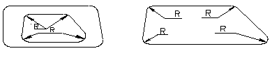
Figure 3.2.1 Minimum value of the fillet radius of the blank
3.3 Blanking parts should avoid narrow cantilever and slot
The depth and width of the convex or concave portion of the blanking member should, in general, be not less than 1.5t (t is the material thickness). At the same time, narrow slits and too narrow slits should be avoided in order to increase the edge strength of the corresponding part of the mold. See Figure 3.3.1.
Figure 3.3.1 Avoiding narrow cantilever and groove
3.4 Punching is preferred for round holes, and punching has a minimum size requirement
Punching is preferred for circular holes. The minimum size of the punch is related to the shape of the hole, the mechanical properties of the material, and the thickness of the material.
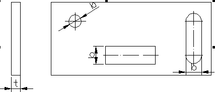
Figure 3.4.1 Example of punch shape
* t is the material thickness, and the minimum size of punching is generally not less than 0.3mm.
Table 1 List of minimum size for punching
3.5 punched hole spacing and hole margin
The minimum distance from the edge of the punched edge of the part depends on the shape of the part and the hole, as shown in Figure 3.5.1. When the edge of the punching is not parallel to the edge of the part, the minimum distance shall be not less than the material thickness t; when parallel, it shall be not less than 1.5t.
Figure 3.5.1 Schematic diagram of hole spacing and hole spacing of blanking parts
3.6 When bending parts and deepening parts punching holes, the distance between the hole wall and the straight wall should be kept at a certain distance.
When bending or deep drawing, the hole wall should be kept at a certain distance from the straight wall of the workpiece (Fig. 3.6.1).
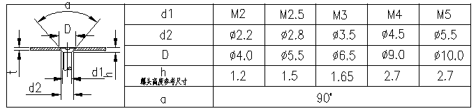
3.7 screws, bolts and through holes countersunk seat
The structural dimensions of the screws, bolt holes and countersunk seats are selected as shown in the following table. For the countersunk head of the countersunk screw, if the plate is too thin to ensure the via d2 and the counterbore D at the same time, the via d2 should be preferentially guaranteed.
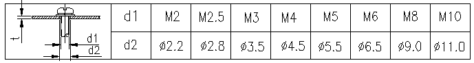
Table 2 Through holes for the screws, bolts
*Requires coffin thickness t≥h.
table 3 Through hole for countersunk head of countersunk screw
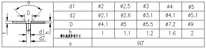
*Requires coffin thickness t≥h.
Table 4 Through hole for countersunk head of countersunk rivet
3.8 blanking burr limits and design mark
3.8.1 Limit values of blanking burrs
The burr of the blanking part is not allowed to exceed a certain height. The limit value (mm) of the burr height of the stamping part is shown in the following table.
* f-level (Precision grade) for higher demand parts;
m level (medium grade) for medium-demand parts;
g level (Rough grade) applies to parts that are generally required.
Table 5 Limits of burr height of stamping parts
3.8.2 Marking requirements for burrs in design drawings
* Raw edge direction: BURR SIDE.
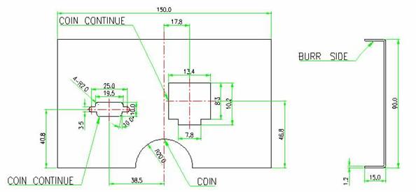 * Parts that require burrs: COIN or COIN CONTINUE. Generally do not fracture the whole structure all the pressure edges, which increases the cost. In the case of using as much as possible the following: exposed fracture; A sharp edge that is often touched by a human hand; a hole or slot that requires a cable; a portion that has a relative sliding.
Figure 3.8.2.1 Example of labeling of burrs in sheet metal structure design drawings
1.1 Scope
This specification specifies the processing requirements that should be noted in the design of sheet metal structures.
This specification applies to the processing requirements that must be observed in the design of sheet metal structures.
1.2 Introduction
The structural parts of our products are mainly made of sheet metal materials. The geometry, size and precision of these stamping parts have a great influence on the stamping process. The stamping parts have good processing technology, which is beneficial to save materials, reduce processes, improve mold life and product quality, and at the same time, effectively reduce product cost.
According to the basic processing methods of sheet metal parts, such as punching, bending, stretching and forming, this specification proposes restrictions on the structural design of sheet metal parts by expounding the process requirements to be paid attention to in each type of processing.
1.3 Keywords
Sheet metal, punching, bending, stretching, forming, nesting, minimum bend radius , burrs, rebound, dead side
2 Normative references
The terms in the following documents become the terms of this specification by reference to this specification. For dated references, all subsequent amendments (not including errata content) or revisions do not apply to this specification. However, parties to agreements based on this Code are encouraged to study whether the latest versions of these documents can be used. For undated references, the latest edition applies to this specification.
| No. | Numbering | name |
| 1 | DKBA0.400.0023 | "Audit process norms" Rev1.0 Author: Deng Ming, Zhou You Guang |
3 blanking
Blanking is divided into ordinary blanking and precision blanking. Due to different processing methods, the processing characteristics of blanking parts are also different. At present, the structural components of our communication products generally only use ordinary punching. The following describes the process of blanking, it refers to a structure of an ordinary blanking process.
3.1 The shape and size of the blanks are as simple and symmetrical as possible, so that the waste is minimized during the layout.
Figure 3.1.1 Layout of blanking parts
3.2 The shape and inner hole of the blanking part should avoid sharp corners.
There must be a circular arc connection at the joint of the straight line or the curve, and the radius of the arc is R≥0.5t. (t is the material wall thickness)
Figure 3.2.1 Minimum value of the fillet radius of the blank
3.3 Blanking parts should avoid narrow cantilever and slot
The depth and width of the convex or concave portion of the blanking member should, in general, be not less than 1.5t (t is the material thickness). At the same time, narrow slits and too narrow slits should be avoided in order to increase the edge strength of the corresponding part of the mold. See Figure 3.3.1.
Figure 3.3.1 Avoiding narrow cantilever and groove
3.4 Punching is preferred for round holes, and punching has a minimum size requirement
Punching is preferred for circular holes. The minimum size of the punch is related to the shape of the hole, the mechanical properties of the material, and the thickness of the material.
Figure 3.4.1 Example of punch shape
|
material |
Round hole diameter b |
Rectangular hole short side width b |
|
High-carbon steel |
1.3t |
1.0t |
|
Low carbon steel, brass |
1.0t |
0.7t |
| aluminum |
0.8t |
0.5t |
* t is the material thickness, and the minimum size of punching is generally not less than 0.3mm.
Table 1 List of minimum size for punching
3.5 punched hole spacing and hole margin
The minimum distance from the edge of the punched edge of the part depends on the shape of the part and the hole, as shown in Figure 3.5.1. When the edge of the punching is not parallel to the edge of the part, the minimum distance shall be not less than the material thickness t; when parallel, it shall be not less than 1.5t.
Figure 3.5.1 Schematic diagram of hole spacing and hole spacing of blanking parts
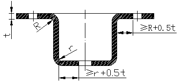
3.6 When bending parts and deepening parts punching holes, the distance between the hole wall and the straight wall should be kept at a certain distance.
When bending or deep drawing, the hole wall should be kept at a certain distance from the straight wall of the workpiece (Fig. 3.6.1).
Figure 3.6.1 Distance between the bent part, the hole wall of the tensile part and the straight wall of the workpiece
3.7 screws, bolts and through holes countersunk seat
The structural dimensions of the screws, bolt holes and countersunk seats are selected as shown in the following table. For the countersunk head of the countersunk screw, if the plate is too thin to ensure the via d2 and the counterbore D at the same time, the via d2 should be preferentially guaranteed.
Table 2 Through holes for the screws, bolts
*Requires coffin thickness t≥h.
table 3 Through hole for countersunk head of countersunk screw
*Requires coffin thickness t≥h.
Table 4 Through hole for countersunk head of countersunk rivet
3.8 blanking burr limits and design mark
3.8.1 Limit values of blanking burrs
The burr of the blanking part is not allowed to exceed a certain height. The limit value (mm) of the burr height of the stamping part is shown in the following table.
| Material wall thickness | Material tensile strength (N/mm2) | |||||||||||
| >100~250 | >250~400 | >400~630 | >630 | |||||||||
| f | m | g | f | m | g | f | m | g | f | M | g | |
| >0.7 ~1.0 | 0.12 | 0.17 | 0.23 | 0.09 | 0.13 | 0.17 | 0.05 | 0.07 | 0.1 | 0.03 | 0.04 | 0.05 |
| >1.0 ~1.6 | 0.17 | 0.25 | 0.34 | 0.12 | 0.18 | 0.24 | 0.07 | 0.11 | 0.15 | 0.04 | 0.06 | 0.08 |
| >1.6 ~2.5 | 0.25 | 0.37 | 0.5 | 0.18 | 0.26 | 0.35 | 0.11 | 0.16 | 0.22 | 0.06 | 0.09 | 0.12 |
| >2.5 ~4.0 | 0.36 | 0.54 | 0.72 | 0.25 | 0.37 | 0.5 | 0.2 | 0.3 | 0.4 | 0.09 | 0.13 | 0.18 |
* f-level (Precision grade) for higher demand parts;
m level (medium grade) for medium-demand parts;
g level (Rough grade) applies to parts that are generally required.
Table 5 Limits of burr height of stamping parts
3.8.2 Marking requirements for burrs in design drawings
* Raw edge direction: BURR SIDE.
Figure 3.8.2.1 Example of labeling of burrs in sheet metal structure design drawings


