Processing Technology of Precision Stainless Steel Nozzle Parts
With the rapid development of aerospace, hydraulic, communications, micro-electronics, medical equipment and other industries. The Turning-Milling composite processing of many small precision composite parts with high precision, multi-batch and complex shape poses a great challenge to the mechanical manufacturing industry. Traditional CNC machining methods and machining processes have been unable to meet the needs of diverse, individualized, and profiled machining. The manufacturing industry is rapidly developing in the direction of high efficiency, precision and compounding.
In view of the characteristics of such parts, most domestic enterprises adopt methods to improve equipment performance and design new processing techniques to meet processing needs and improve production efficiency. This paper takes a typical composite nozzle part as an example, and uses the characteristics and advantages of B0326-II precision automatic lathe. From the aspects of tool selection, machining process development, key machining route design and trial processing problem analysis, in-depth processing technology research was carried out. The problem of large batch size, low efficiency and difficult processing of such parts is solved.
1. Analysis of parts processing technology
Parts technical requirements
Figure 1 shows the nozzle parts in a medical device. The monthly output is 20,000 pieces, the material is stainless steel 1Cr18Ni9Ti, which is a difficult material; The machining elements of this part are more, including turning outer circle and thread, milling flat surface; Drilling center hole and bottom hole, boring hole, tapping thread, etc. In addition, the dimensional accuracy and surface roughness of the parts are required to be high, and the coaxiality of the holes at both ends is 0.02 mm.
Based on the above analysis, the processing difficulties of the part: Guarantee the dimensional accuracy of the outer and inner holes, the coaxiality requirements of the two inner holes, and mass production.
Nozzle part processing
B0326-II precision automatic lathe is mainly used for turning. It also has drilling, engraving, milling groove, milling teeth, tapping, reaming and so on. The multi-process combined machining precision machine tool has C-axis and Y-axis indexing functions, which can perform radial plane milling, drilling, tapping and other processes. The double spindle control system can realize the automatic positioning and feeding of the back axle after the spindle side processing, and effectively solve the problem of low efficiency and accuracy caused by the turning of the workpiece.
As shown in Figure 2, according to the characteristics of the machine tool, the design of the outer contour processing route of the part: Spindle side→ Turning end face→ Turning the outer circle to 39mm.→ Turning the outer circle to 65.1mm to the rear axle side car end.
According to the above analysis, the processing design of nozzle parts is shown in Table 1.
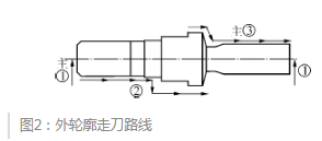
Outer contour cutter path
2. The key step of the design process
Left hole machining
The left side hole is machined on the T31-T35 five hole tool holder on the spindle side. The five-hole tool holder has a compact layout, which reduces the time for the tool to pass the knife and has high processing efficiency.
Bore hole Φ7 has higher precision requirement and adopts boring process. The hole depth of 38mm belongs to deep hole processing. The difficulty lies in the cooling of the cutting area of the drill bit during the drilling of the hole and the problem of chip removal. High pressure oil cooling and G83 pecking drill can effectively prevent breakage and chip entanglement.
Specific steps:
Firstly, drill the center hole of about 2mm with Φ6 center drill, the depth should not be too shallow, otherwise the hole chamfer will have burrs; Then drill with Φ5.8 drill bit, leaving a machining allowance of about 0.5mm on one side. Due to the high hardness of the part material, most of the remaining amount should be removed in the process, and high pressure oil cooling should be turned on; Finally, the hole size is ensured by boring, and the cutting mode is high speed and low feed mode. S25.0G-SVNR12SN boring bar is selected, blade type VNBR0620-01, spindle speed 3000r/min, cutting depth ap=0.25mm, feed rate f=0.02mm/r.
Turning the outer circle to 39mm
This step is the outer contour processing, focusing on how to improve the processing efficiency and ensure the surface quality. Consider the structural characteristics of the part and the material properties. The route design of the cutter is shown in Figure 3. This step 〖LL〗 〖JP2〗 is completed in three times. The first two uses the G90 rectangular path to remove most of the allowance and the third finish. In the first two times, the G90 rectangular cutter path was used to remove most of the allowance. The finishing is completed for the third time.
When the first rectangular machining route is executed, it is processed to point A, each time cutting depth is 0.5mm, the feed speed is 0.05mm/r, and it is completed by three knives; When the second rectangular machining route is executed, it is processed to point B, each time cutting depth is 0.3mm, the feed speed is 0.03mm/r, and the four-knife is completed; The final finishing depth is 0.1 mm and the feed rate is 0.01 mm/r. This step uses Kyocera SCLCR1616H-12 external round knife, blade type CCGT09T304M, the surface quality of the parts is better.
Figure 3. Turning the outer circle to 39mm and taking the cutter path
Left turning thread
Since the M10 thread needs to be matched with other medical device parts, it is required to control the thread diameter and the roughness value reaches Ra0.8.
To meet the requirements, thread turning in three steps:
first step, The outer circular knife will turn the large diameter by 0.2mm;
The second step, After the thread turning is completed for the first time, the outer circular knife is again called to turn along the thread surface to remove the top burr, but the burr is pressed toward the bottom of the tooth;
third step, Turn the last two knives along the threads with a threading cutter, and then turn them again to remove the burrs in the direction of the bottom of the tooth in the second step.
Milling flat
The plane milling mainly utilizes the spindle C-axis indexing function of the B0326-II precision automatic lathe to effectively solve the secondary clamping problem. The total milling layer thickness of this step is 2.3mm, and a large diameter end mill can be selected to improve the processing efficiency.
According to the analysis, the diameter Φ10 end mill is selected. After the spindle is braked, it is divided into three milling machines.
first time, the milling depth was 0.65 mm.
The second time, the milling depth is 0.65mm.
For the third time, the milling depth is 0.35 mm.
Each time the milling feed rate is 50mm/min, the C-axis is indexed by 180° and the other side is machined. After the plane milling is finished, there will be burrs on the outer end of the plane. At this time, it is better to use an external circular knife to deburr along the outer circle of Φ13, and the effect is better.
Turning the outer circle to 65.1mm
The difficulty in external turning here is that the C area is groove-shaped, which limits the tool angle and makes it difficult to cut the knife. Conventional circular cutting tools are easy to interfere and collapse, and the surface quality of grooves is poor.
Therefore, the turning is carried out three times, and the path of the cutting is shown in Figure 4. For the first time, the groove cutter with 3 mm width is selected to cut to the bottom of the groove with 0.1 mm finishing allowance, and the tool is fed along Route 1 to provide the cutting space for the next turning.
For the second time, the conventional 90° external turning tool is selected, and the tool is fed along the route 2, and processed according to the G90 rectangular route, and the total amount of 6.4 mm is removed;
the third time, Use the rear sweep tool and along Route 3 for finishing.Due to the small space in the groove, the 90° outer circular cutter cutting edge is easy to interfere. The use of the rear sweeping knife can effectively solve the problem and ensure the roughness value at the bottom of the groove.
Figure 4. Turning the outer circle to 65.1mm and taking the cutter path
The back shaft receiving hole drilling
As shown in Figure 5. After all the machining on the main shaft side is completed, the cutting knife is positioned to the cutting position, the back shaft is centered with the main shaft, the back shaft T9900 is clamped along the main shaft direction B-B, and the main back shaft is simultaneously rotated, which greatly increases the rigidity. Cut the back shaft to pick up the material, and use the back side T35, T36, T37 tool to carry out the end face and drill hole. The back axis is automatically positioned to be clamped with the spindle concentric position, avoiding the coaxiality error caused by re-clamping, ensuring the coaxiality requirements of the holes Φ7 and Φ4, and solving the problem of coaxiality processing of the part.
Figure 5. Sketch of rear axle connection
3. Trial processing problem analysis
After the processing technology is drafted, the programming is carried out. After repeated simulation verification, the first trial processing of the part showed a burr upturn at the bottom of the Φ7 hole. Φ4 orifice without 60° chamfer. Φ7 hole depth deviation and other issues.
The Φ7 hole size accuracy and surface quality of this part are high. When the Φ5 drill bit is drilled to the bottom of the hole, the chip is not discharged in time due to the extrusion, which causes the burr at the bottom of the hole to be turned up, which affects the quality of the part. After repeated trials, make the following adjustments: When the drill bit is drilled to the bottom of the hole, the drill does not directly exit, lift 0.1mm along the hole, then delay 0.2s (ie G04U0.2) and then leave the bottom of the hole to remove the upturn burr.
As shown in Figure 6. The Φ4 hole chamfer is machined from Φ6 center drill. The no-chamfering of the orifice is judged as the center hole is drilled too deep, and the cone surface has exceeded 60° at the bottom of the center drill hole, and the wear compensation +0.5 on the back-axis side T36 can solve the problem.
Figure 6. Φ4 hole 60° chamfering diagram
When the first product was tested, it was found that the depth of Φ7 hole was 37.8mm, which was 0.2mm smaller than the actual size. The reason for the analysis is mainly the T23 boring tool on the spindle side, and there is a deviation in the tool setting. On the spindle side T23 boring tool re-aligns the tool accurately, and the T23 wear compensation input +0.2. After repeated debugging, the nozzle parts meet the acceptance requirements, and the processing nozzles are shown in Figure 7.
4. Summary
After the commissioning of the nozzle parts, the machine tool is equipped with an automatic feeder. The feeding, processing, receiving and discharging are completely automated, and the processing demand of 20,000 pieces per month is realized. It solves the problems of miniaturization, multi-variety, high-volume and high-precision that occur in modern manufacturing processes.
Through the research of B0326-II precision automatic lathe small composite shaft parts processing technology. It provides technical basis for the promotion of new type of turning and milling combined machining technology, and also provides reference and reference for processing similar parts.
In view of the characteristics of such parts, most domestic enterprises adopt methods to improve equipment performance and design new processing techniques to meet processing needs and improve production efficiency. This paper takes a typical composite nozzle part as an example, and uses the characteristics and advantages of B0326-II precision automatic lathe. From the aspects of tool selection, machining process development, key machining route design and trial processing problem analysis, in-depth processing technology research was carried out. The problem of large batch size, low efficiency and difficult processing of such parts is solved.
1. Analysis of parts processing technology
Parts technical requirements
Figure 1 shows the nozzle parts in a medical device. The monthly output is 20,000 pieces, the material is stainless steel 1Cr18Ni9Ti, which is a difficult material; The machining elements of this part are more, including turning outer circle and thread, milling flat surface; Drilling center hole and bottom hole, boring hole, tapping thread, etc. In addition, the dimensional accuracy and surface roughness of the parts are required to be high, and the coaxiality of the holes at both ends is 0.02 mm.
Based on the above analysis, the processing difficulties of the part: Guarantee the dimensional accuracy of the outer and inner holes, the coaxiality requirements of the two inner holes, and mass production.
Nozzle part processing
B0326-II precision automatic lathe is mainly used for turning. It also has drilling, engraving, milling groove, milling teeth, tapping, reaming and so on. The multi-process combined machining precision machine tool has C-axis and Y-axis indexing functions, which can perform radial plane milling, drilling, tapping and other processes. The double spindle control system can realize the automatic positioning and feeding of the back axle after the spindle side processing, and effectively solve the problem of low efficiency and accuracy caused by the turning of the workpiece.
As shown in Figure 2, according to the characteristics of the machine tool, the design of the outer contour processing route of the part: Spindle side→ Turning end face→ Turning the outer circle to 39mm.→ Turning the outer circle to 65.1mm to the rear axle side car end.
According to the above analysis, the processing design of nozzle parts is shown in Table 1.
Outer contour cutter path
Nozzle part processing design process table
2. The key step of the design process
Left hole machining
The left side hole is machined on the T31-T35 five hole tool holder on the spindle side. The five-hole tool holder has a compact layout, which reduces the time for the tool to pass the knife and has high processing efficiency.
Bore hole Φ7 has higher precision requirement and adopts boring process. The hole depth of 38mm belongs to deep hole processing. The difficulty lies in the cooling of the cutting area of the drill bit during the drilling of the hole and the problem of chip removal. High pressure oil cooling and G83 pecking drill can effectively prevent breakage and chip entanglement.
Specific steps:
Firstly, drill the center hole of about 2mm with Φ6 center drill, the depth should not be too shallow, otherwise the hole chamfer will have burrs; Then drill with Φ5.8 drill bit, leaving a machining allowance of about 0.5mm on one side. Due to the high hardness of the part material, most of the remaining amount should be removed in the process, and high pressure oil cooling should be turned on; Finally, the hole size is ensured by boring, and the cutting mode is high speed and low feed mode. S25.0G-SVNR12SN boring bar is selected, blade type VNBR0620-01, spindle speed 3000r/min, cutting depth ap=0.25mm, feed rate f=0.02mm/r.
Turning the outer circle to 39mm
This step is the outer contour processing, focusing on how to improve the processing efficiency and ensure the surface quality. Consider the structural characteristics of the part and the material properties. The route design of the cutter is shown in Figure 3. This step 〖LL〗 〖JP2〗 is completed in three times. The first two uses the G90 rectangular path to remove most of the allowance and the third finish. In the first two times, the G90 rectangular cutter path was used to remove most of the allowance. The finishing is completed for the third time.
When the first rectangular machining route is executed, it is processed to point A, each time cutting depth is 0.5mm, the feed speed is 0.05mm/r, and it is completed by three knives; When the second rectangular machining route is executed, it is processed to point B, each time cutting depth is 0.3mm, the feed speed is 0.03mm/r, and the four-knife is completed; The final finishing depth is 0.1 mm and the feed rate is 0.01 mm/r. This step uses Kyocera SCLCR1616H-12 external round knife, blade type CCGT09T304M, the surface quality of the parts is better.
Figure 3. Turning the outer circle to 39mm and taking the cutter path
Left turning thread
Since the M10 thread needs to be matched with other medical device parts, it is required to control the thread diameter and the roughness value reaches Ra0.8.
To meet the requirements, thread turning in three steps:
first step, The outer circular knife will turn the large diameter by 0.2mm;
The second step, After the thread turning is completed for the first time, the outer circular knife is again called to turn along the thread surface to remove the top burr, but the burr is pressed toward the bottom of the tooth;
third step, Turn the last two knives along the threads with a threading cutter, and then turn them again to remove the burrs in the direction of the bottom of the tooth in the second step.
Milling flat
The plane milling mainly utilizes the spindle C-axis indexing function of the B0326-II precision automatic lathe to effectively solve the secondary clamping problem. The total milling layer thickness of this step is 2.3mm, and a large diameter end mill can be selected to improve the processing efficiency.
According to the analysis, the diameter Φ10 end mill is selected. After the spindle is braked, it is divided into three milling machines.
first time, the milling depth was 0.65 mm.
The second time, the milling depth is 0.65mm.
For the third time, the milling depth is 0.35 mm.
Each time the milling feed rate is 50mm/min, the C-axis is indexed by 180° and the other side is machined. After the plane milling is finished, there will be burrs on the outer end of the plane. At this time, it is better to use an external circular knife to deburr along the outer circle of Φ13, and the effect is better.
Turning the outer circle to 65.1mm
The difficulty in external turning here is that the C area is groove-shaped, which limits the tool angle and makes it difficult to cut the knife. Conventional circular cutting tools are easy to interfere and collapse, and the surface quality of grooves is poor.
Therefore, the turning is carried out three times, and the path of the cutting is shown in Figure 4. For the first time, the groove cutter with 3 mm width is selected to cut to the bottom of the groove with 0.1 mm finishing allowance, and the tool is fed along Route 1 to provide the cutting space for the next turning.
For the second time, the conventional 90° external turning tool is selected, and the tool is fed along the route 2, and processed according to the G90 rectangular route, and the total amount of 6.4 mm is removed;
the third time, Use the rear sweep tool and along Route 3 for finishing.Due to the small space in the groove, the 90° outer circular cutter cutting edge is easy to interfere. The use of the rear sweeping knife can effectively solve the problem and ensure the roughness value at the bottom of the groove.
Figure 4. Turning the outer circle to 65.1mm and taking the cutter path
The back shaft receiving hole drilling
As shown in Figure 5. After all the machining on the main shaft side is completed, the cutting knife is positioned to the cutting position, the back shaft is centered with the main shaft, the back shaft T9900 is clamped along the main shaft direction B-B, and the main back shaft is simultaneously rotated, which greatly increases the rigidity. Cut the back shaft to pick up the material, and use the back side T35, T36, T37 tool to carry out the end face and drill hole. The back axis is automatically positioned to be clamped with the spindle concentric position, avoiding the coaxiality error caused by re-clamping, ensuring the coaxiality requirements of the holes Φ7 and Φ4, and solving the problem of coaxiality processing of the part.
Figure 5. Sketch of rear axle connection
3. Trial processing problem analysis
After the processing technology is drafted, the programming is carried out. After repeated simulation verification, the first trial processing of the part showed a burr upturn at the bottom of the Φ7 hole. Φ4 orifice without 60° chamfer. Φ7 hole depth deviation and other issues.
The Φ7 hole size accuracy and surface quality of this part are high. When the Φ5 drill bit is drilled to the bottom of the hole, the chip is not discharged in time due to the extrusion, which causes the burr at the bottom of the hole to be turned up, which affects the quality of the part. After repeated trials, make the following adjustments: When the drill bit is drilled to the bottom of the hole, the drill does not directly exit, lift 0.1mm along the hole, then delay 0.2s (ie G04U0.2) and then leave the bottom of the hole to remove the upturn burr.
As shown in Figure 6. The Φ4 hole chamfer is machined from Φ6 center drill. The no-chamfering of the orifice is judged as the center hole is drilled too deep, and the cone surface has exceeded 60° at the bottom of the center drill hole, and the wear compensation +0.5 on the back-axis side T36 can solve the problem.
Figure 6. Φ4 hole 60° chamfering diagram
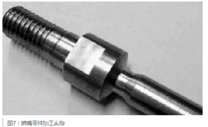
When the first product was tested, it was found that the depth of Φ7 hole was 37.8mm, which was 0.2mm smaller than the actual size. The reason for the analysis is mainly the T23 boring tool on the spindle side, and there is a deviation in the tool setting. On the spindle side T23 boring tool re-aligns the tool accurately, and the T23 wear compensation input +0.2. After repeated debugging, the nozzle parts meet the acceptance requirements, and the processing nozzles are shown in Figure 7.
Figure 7. Stainless steel nozzle parts processing physical
4. Summary
After the commissioning of the nozzle parts, the machine tool is equipped with an automatic feeder. The feeding, processing, receiving and discharging are completely automated, and the processing demand of 20,000 pieces per month is realized. It solves the problems of miniaturization, multi-variety, high-volume and high-precision that occur in modern manufacturing processes.
Through the research of B0326-II precision automatic lathe small composite shaft parts processing technology. It provides technical basis for the promotion of new type of turning and milling combined machining technology, and also provides reference and reference for processing similar parts.


