Precision machining solution for crankshaft holes
The machining quality of the crankshaft bore has a major impact on the performance of the engine. Chery Engine Division has continuously researched and continuously improved the finishing plan of the crankshaft hole of cast iron engine cylinder according to the actual processing conditions, and achieved remarkable results. The processing quality and efficiency have been effectively improved.
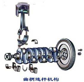
The cylinder block is an important basic part of the engine, and its main function is to assemble the various mechanisms and systems into one. The most important moving parts of the engine - the crankshaft, the piston and the connecting rod - have a very close relationship with the cylinder. Figure 1 is a schematic view of a crank linkage mechanism. At present, our common gasoline engine has a maximum speed of more than 6000r/min. The crankshaft forms an oil film between the crankshaft hole of the engine block and the bearing bush, and supports and lubricates the high-speed running crankshaft by means of a sliding bearing. This puts forward a high process requirement for the precision machining of the crankshaft hole.
Since the machining quality of the crankshaft hole has a great influence on the performance of the engine, the requirements for the engine crankshaft hole process are generally strict. Including diameter, position, roundness, straightness of the center of each crankshaft hole and surface roughness. In order to meet these demanding process specifications, precision machining generally uses either fine boring or hinged machining.
I. Analysis of precision boring processing
The precision boring method is used to machine the crankshaft hole, and the initial input cost is lower than the hinge method. It can be arranged in the same process as the finishing of other parts in the machining center or special equipment.
Due to the special process requirements, the fine solution we are currently using is a combination of two precision boring tools:
The first fine boring tool guides the crankshaft holes of the first and second gears (see Figure 2).
The second fine boring tool is finely supported by the remaining crankshaft holes under the support of the first and second gear crankshaft holes (see Figure 3).
Since the crankshaft holes need to maintain a high degree of coaxiality between the gears, it is necessary to feed in the same direction during finishing. However, when such a long crankshaft boring tool is machining the first-speed crankshaft hole, there is a case where the jump is excessive due to lack of support. Therefore, the crankshaft hole is finished by combining one long and one short boring tool.
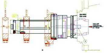
figure 2 Fine boring tool for machining 1 and 2 crankshaft holes
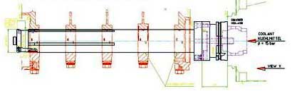
image 3 Fine boring tool for machining the last few crankshaft holes
At present, the boring tool for the fine crankshaft hole is generally made of cemented carbide or CBN. Cemented carbide inserts are less expensive, but the surface roughness of the machined workpiece is not good and the durability of the insert is low. In response to this problem, we have collaborated with tool suppliers to collect the most common blade coating materials in the industry. Cutting experiments were performed on 16 carbide inserts using different techniques of cutting angles. And tried to optimize various suitable processing parameters, the specific roughness fluctuations are shown in Figure 4. Through a large number of verifications, the best experimental results of cemented carbide inserts satisfying the process requirements such as roughness are 80 pieces in one time. Still can not meet the requirements of mass production.
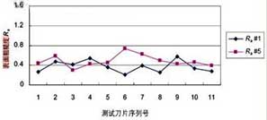
Figure 4 In the test of carbide inserts, partially meet the required blade roughness fluctuations
Subsequently, we verified another solution for the blade material of the fine boring tool, that is, replacing the existing cemented carbide blade material with CBN blade material. We rely on tool suppliers to develop more than 10 different CBN inserts for cutting verification of the crankshaft bore. The test results show: In terms of roughness control, the CBN insert is significantly superior to the carbide insert and has a processing life of over 200 pieces. But at the same time it has also produced some new problems: When about 150 pieces are machined with a CBN blade, slight burrs appear on the side of the hole, and in the case of severe, there will be a flanging phenomenon. The burrs and even the flanging here become quality hazards that affect the performance of the engine. In severe cases, it will cause quality accidents such as bush scratches and crankshaft locks. In the handling of the crankshaft hole burr problem, we increased the brush of the crankshaft hole, which relieved the existence of the burr to some extent, but there is still a large quality risk. In addition, the quality stability of the crankshaft hole sizing scheme is poor compared to the hinge, and the risk of quality control is greatly increased because of the frequent tool change. The surface roughness variation of the workpiece produced by the fine boring tool decreases rapidly as the tool durability decreases. A comparison of the surface roughness of a workpiece machined with a CBN insert in a fine crankshaft bore is shown in Figures 5 and 6.
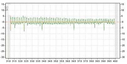
Figure 5 Report on the surface roughness of the blade after boring the first hole
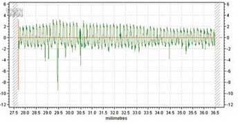
Figure 6 Surface roughness report when boring machine processing 200 pieces
two, Analysis of hinge processing
We have done a lot of exploration work on the crankshaft hole scheme for boring precision machining. We have developed a variety of new inserts for machining verification, but still have not achieved the desired processing results, so we consider the crankshaft reaming scheme again. From the perspective of cost, the one-time investment of the crankshaft hole hinge is large. The preliminary offer from a well-known German honing machine manufacturer is 400,000 Euros (prices vary depending on configuration requirements). However, the post-processing cost of the hinge is much lower than that of the fine boring, and the processing quality is stable. The specific implementation of the crankshaft hole hinge scheme is shown in FIG.
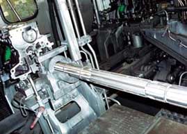
Figure 7 Implementation of crankshaft hole hinge scheme
The crankshaft hole hinge is machined using a horizontal honing machine. Because the horizontal honing machine has a long working stroke, it is suitable for deep hole honing such as crankshaft holes, and the depth can be up to 3000mm. During the processing, the whetstone of the honing head is fed radially under the action of the expansion and contraction mechanism, and the workpiece is gradually processed to the required size. The outer circumference of the honing head is set with 2 to 10 oil stones with a length of about 1/3 to 3/4 of the hole length, and both the rotary motion and the reciprocating motion during the boring. At the same time, it is uniformly raised by the spring or hydraulic control in the honing head, so the contact area with the surface of the hole is large, and the processing efficiency is high.
The honing allowance is generally not more than 0.2mm. For the processing of cast iron or non-ferrous metals, the circumferential speed of honing can reach more than 50m/min; the reciprocating speed of honing should not exceed 15~20m/min. The pressure of the oil stone on the hole wall is generally 0.3-0.5 MPa, the rough boring can reach about 1 MPa, and the fine boring can be less than 0.1 MPa. Since the whetstone is in surface contact with the workpiece during honing, the vertical pressure of each abrasive particle on the surface of the workpiece is only 1/50 to 1/100 of that when grinding. In addition, the honing speed is low, so the temperature of the cutting zone can be maintained in the range of 50 ° C ~ 150 ° C, which is beneficial to reduce the residual stress on the machined surface and improve the surface quality. In order to wash the chips, avoid blocking the oil stone, and reduce the temperature and surface roughness of the cutting zone, the cutting fluid used in the honing must have a certain working pressure and be filtered. Most of the cutting fluids use kerosene or kerosene plus spindle oil, and extreme pressure emulsions can also be used.
It is analyzed from the fluctuation trend of the roughness measurement report data in Fig. 8. The processing stability of the hinge is very high, and the durability of the sanding head can be processed more than 10,000 pieces at a time, and the production efficiency is greatly improved. With the CBN blade's fine machining method, every 200 pieces need to be changed once, and the average tool change and the first piece inspection takes 42 minutes. If the time it takes to change the tool frequently is converted to each workpiece, it will lose 12.6s/piece. According to the existing processing line of 120s / piece, the production of parts is 160,000 pieces / year, the annual processing loss will be 2.016 million s, using this time can be processed more than 16,800 pieces per year.
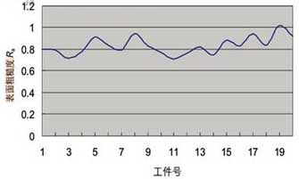
Figure 8 Product roughness measurement report after 20 days of implementation of the hinged production program
The table shows the cost loss of the tool loss caused by different finishing methods of the crankshaft hole. From the table, it can be analyzed that the tool cost difference of the single piece is more obvious. According to the analysis and calculation, when the 1.03 million pieces are produced, the tool loss of the hinged solution is about 3.81 million yuan compared with the CBN precision solution, which is slightly the same as the price of the hinged device. The quality control of the hinged solution is much less difficult and risky.
The cylinder block is an important basic part of the engine, and its main function is to assemble the various mechanisms and systems into one. The most important moving parts of the engine - the crankshaft, the piston and the connecting rod - have a very close relationship with the cylinder. Figure 1 is a schematic view of a crank linkage mechanism. At present, our common gasoline engine has a maximum speed of more than 6000r/min. The crankshaft forms an oil film between the crankshaft hole of the engine block and the bearing bush, and supports and lubricates the high-speed running crankshaft by means of a sliding bearing. This puts forward a high process requirement for the precision machining of the crankshaft hole.
Since the machining quality of the crankshaft hole has a great influence on the performance of the engine, the requirements for the engine crankshaft hole process are generally strict. Including diameter, position, roundness, straightness of the center of each crankshaft hole and surface roughness. In order to meet these demanding process specifications, precision machining generally uses either fine boring or hinged machining.
I. Analysis of precision boring processing
The precision boring method is used to machine the crankshaft hole, and the initial input cost is lower than the hinge method. It can be arranged in the same process as the finishing of other parts in the machining center or special equipment.
Due to the special process requirements, the fine solution we are currently using is a combination of two precision boring tools:
The first fine boring tool guides the crankshaft holes of the first and second gears (see Figure 2).
The second fine boring tool is finely supported by the remaining crankshaft holes under the support of the first and second gear crankshaft holes (see Figure 3).
Since the crankshaft holes need to maintain a high degree of coaxiality between the gears, it is necessary to feed in the same direction during finishing. However, when such a long crankshaft boring tool is machining the first-speed crankshaft hole, there is a case where the jump is excessive due to lack of support. Therefore, the crankshaft hole is finished by combining one long and one short boring tool.
figure 2 Fine boring tool for machining 1 and 2 crankshaft holes
image 3 Fine boring tool for machining the last few crankshaft holes
At present, the boring tool for the fine crankshaft hole is generally made of cemented carbide or CBN. Cemented carbide inserts are less expensive, but the surface roughness of the machined workpiece is not good and the durability of the insert is low. In response to this problem, we have collaborated with tool suppliers to collect the most common blade coating materials in the industry. Cutting experiments were performed on 16 carbide inserts using different techniques of cutting angles. And tried to optimize various suitable processing parameters, the specific roughness fluctuations are shown in Figure 4. Through a large number of verifications, the best experimental results of cemented carbide inserts satisfying the process requirements such as roughness are 80 pieces in one time. Still can not meet the requirements of mass production.
Figure 4 In the test of carbide inserts, partially meet the required blade roughness fluctuations
Subsequently, we verified another solution for the blade material of the fine boring tool, that is, replacing the existing cemented carbide blade material with CBN blade material. We rely on tool suppliers to develop more than 10 different CBN inserts for cutting verification of the crankshaft bore. The test results show: In terms of roughness control, the CBN insert is significantly superior to the carbide insert and has a processing life of over 200 pieces. But at the same time it has also produced some new problems: When about 150 pieces are machined with a CBN blade, slight burrs appear on the side of the hole, and in the case of severe, there will be a flanging phenomenon. The burrs and even the flanging here become quality hazards that affect the performance of the engine. In severe cases, it will cause quality accidents such as bush scratches and crankshaft locks. In the handling of the crankshaft hole burr problem, we increased the brush of the crankshaft hole, which relieved the existence of the burr to some extent, but there is still a large quality risk. In addition, the quality stability of the crankshaft hole sizing scheme is poor compared to the hinge, and the risk of quality control is greatly increased because of the frequent tool change. The surface roughness variation of the workpiece produced by the fine boring tool decreases rapidly as the tool durability decreases. A comparison of the surface roughness of a workpiece machined with a CBN insert in a fine crankshaft bore is shown in Figures 5 and 6.
Figure 5 Report on the surface roughness of the blade after boring the first hole
Figure 6 Surface roughness report when boring machine processing 200 pieces
two, Analysis of hinge processing
We have done a lot of exploration work on the crankshaft hole scheme for boring precision machining. We have developed a variety of new inserts for machining verification, but still have not achieved the desired processing results, so we consider the crankshaft reaming scheme again. From the perspective of cost, the one-time investment of the crankshaft hole hinge is large. The preliminary offer from a well-known German honing machine manufacturer is 400,000 Euros (prices vary depending on configuration requirements). However, the post-processing cost of the hinge is much lower than that of the fine boring, and the processing quality is stable. The specific implementation of the crankshaft hole hinge scheme is shown in FIG.
Figure 7 Implementation of crankshaft hole hinge scheme
The crankshaft hole hinge is machined using a horizontal honing machine. Because the horizontal honing machine has a long working stroke, it is suitable for deep hole honing such as crankshaft holes, and the depth can be up to 3000mm. During the processing, the whetstone of the honing head is fed radially under the action of the expansion and contraction mechanism, and the workpiece is gradually processed to the required size. The outer circumference of the honing head is set with 2 to 10 oil stones with a length of about 1/3 to 3/4 of the hole length, and both the rotary motion and the reciprocating motion during the boring. At the same time, it is uniformly raised by the spring or hydraulic control in the honing head, so the contact area with the surface of the hole is large, and the processing efficiency is high.
The honing allowance is generally not more than 0.2mm. For the processing of cast iron or non-ferrous metals, the circumferential speed of honing can reach more than 50m/min; the reciprocating speed of honing should not exceed 15~20m/min. The pressure of the oil stone on the hole wall is generally 0.3-0.5 MPa, the rough boring can reach about 1 MPa, and the fine boring can be less than 0.1 MPa. Since the whetstone is in surface contact with the workpiece during honing, the vertical pressure of each abrasive particle on the surface of the workpiece is only 1/50 to 1/100 of that when grinding. In addition, the honing speed is low, so the temperature of the cutting zone can be maintained in the range of 50 ° C ~ 150 ° C, which is beneficial to reduce the residual stress on the machined surface and improve the surface quality. In order to wash the chips, avoid blocking the oil stone, and reduce the temperature and surface roughness of the cutting zone, the cutting fluid used in the honing must have a certain working pressure and be filtered. Most of the cutting fluids use kerosene or kerosene plus spindle oil, and extreme pressure emulsions can also be used.
It is analyzed from the fluctuation trend of the roughness measurement report data in Fig. 8. The processing stability of the hinge is very high, and the durability of the sanding head can be processed more than 10,000 pieces at a time, and the production efficiency is greatly improved. With the CBN blade's fine machining method, every 200 pieces need to be changed once, and the average tool change and the first piece inspection takes 42 minutes. If the time it takes to change the tool frequently is converted to each workpiece, it will lose 12.6s/piece. According to the existing processing line of 120s / piece, the production of parts is 160,000 pieces / year, the annual processing loss will be 2.016 million s, using this time can be processed more than 16,800 pieces per year.
Figure 8 Product roughness measurement report after 20 days of implementation of the hinged production program
The table shows the cost loss of the tool loss caused by different finishing methods of the crankshaft hole. From the table, it can be analyzed that the tool cost difference of the single piece is more obvious. According to the analysis and calculation, when the 1.03 million pieces are produced, the tool loss of the hinged solution is about 3.81 million yuan compared with the CBN precision solution, which is slightly the same as the price of the hinged device. The quality control of the hinged solution is much less difficult and risky.


