Drilling of micro-holes in circuit board composites
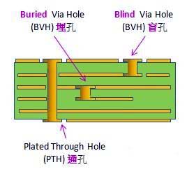
The specifications of printed circuit boards are complex and there are many types of products. The most widely used epoxy resin-based composite material in printed circuit boards is a micro hole (a small hole with a diameter of 0.6 mm or less and a micro hole with a diameter of 0.3 mm or less).
The composite circuit board has high brittleness, high hardness, high fiber strength, high toughness, low interlaminar shear strength, anisotropy, poor thermal conductivity, and a large difference in thermal expansion coefficients of fibers and resins. When the cutting temperature is high, it is easy to generate thermal stress at the fiber-substrate interface around the cutting zone; When the temperature is too high, the resin melts and sticks to the cutting edge, which makes processing and chip removal difficult.
The cutting force of the drilled composite material is very uneven, and it is easy to cause defects such as delamination, burrs and cracks, and the processing quality is difficult to ensure. This material is extremely abrasive to the tool and the tool wear is quite severe. The wear of the tool in turn leads to greater cutting forces and heat generation. If the heat cannot be dissipated in time, it will cause melting of the low melting point component in the PCB material and peeling between the composite layer and the layer. Therefore, PCB composite materials are difficult to process non-metal composite materials, and the processing mechanism is completely different from that of metal materials.
When mechanically drilling PCB materials, the processing efficiency is high, the hole positioning is accurate, and the quality of the holes is also high. However, when drilling a micro hole, the diameter of the drill bit is too small and it is easy to break. Defects such as material delamination, hole wall damage, burrs and stains may also occur during the drilling process.
I. Drilling force
Various problems occurring during mechanical drilling are directly or indirectly related to axial force and cutting torque. The main factors affecting axial force and torque are the feed rate, cutting speed, fiber bundle shape and the presence or absence of pre-formed holes that also have an effect on axial forces and torque. The axial force and torque increase with increasing feed rate and cutting speed. As the feed rate increases, the thickness of the cutting layer increases, and as the cutting speed increases, the number of cut fibers per unit time increases, and the amount of tool wear increases rapidly, so the axial force and torque increase.
The axial force can be divided into static component force FS and dynamic component force FD. The component force of the axial force has different effects on the cutting edge, and the static component force FS of the axial force affects the cutting of the chisel edge. The dynamic component force FD mainly affects the cutting of the main cutting edge, and the dynamic component force FD has a greater influence on the surface roughness than the static component force FS. The axial force increases with the feed rate, and the influence of the cutting speed on the axial force is not obvious. In addition, in the case of prefabricated holes, when the aperture is less than 0.4 mm, the static component force FS decreases sharply with the increase of the aperture, while the dynamic component FD decreases with a flattening tendency.
Due to the different processing properties of the composite matrix and the reinforcing fibers, the matrix resin and the fibers have different effects on the axial force during mechanical drilling. Khashaba studied the effects of matrix and fiber types on axial forces and torque:
It was found that the shape of the fiber bundle had a significant influence on the axial force, and the type of the matrix resin had little effect on the axial force.
II. Wear and break of the drill bit
PCB composite micro-drill wear includes chemical wear and friction wear. Chemical wear is caused by chemical attack of the pyrolysis product released from the PCB material on the Co binder in the micro-drilled material WC-Co cemented carbide. At about 300 ° C, this erosion reaction has become more apparent. At a drilling speed of less than 150 mm/min, chemical wear is no longer the main form of wear, and friction and wear become the main form of wear. The wear of the PCB micro-drill is also related to the ratio of cutting speed, feed rate and bit radius to fiber bundle width. Research by Inoue et al. shows that: The ratio of the radius of the drill to the width of the fiber bundle (glass fiber) has a great influence on the tool life. The larger the ratio, the larger the fiber bundle width of the cutter and the larger the tool wear.
In practical applications, the new drill bit drills up to 2,500 holes for grinding.
Grinding the drill bit for the first time, drilling up to 2000 holes, and grinding it again.
The second grinding of the drill bit, drilling up to 1500 holes, need to be ground again,
The third time the drill bit was drilled, drilling up to 1000 holes and the drill bit was scrapped.
During the micropore processing of the PCB, the axial force and torque increase with the increase of the feed rate and the drilling depth, and the main reason is related to the chip removal state. As the drilling depth increases, the chip discharge is difficult: In this case, the cutting temperature rises, the resin material melts and firmly bonds the glass fibers and the copper foil pieces to form a tough cutting body. This cutting body has an affinity with the PCB matrix material. Once such a cutting body is produced, the discharge of the chips is stopped, and the axial force and torque are sharply increased, thereby causing the microporous drill bit to break. The fracture form of the PCB micro-hole drill bit has buckling, torsion breaking and buckling and torsion breaking, and generally both coexist. The breaking condition is mainly chip clogging, which is a key factor causing the increase of drilling torque. Reducing the axial force and cutting torque is the key to reducing the breakage of the micro-hole drill.
III. Drilled damage form
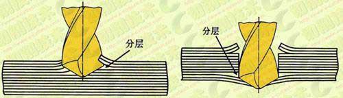
1, layering
Various damage may occur during mechanical drilling of GFRP (glass fiber reinforced) laminates. The most serious of these is interlayer delamination, which results in a sharp drop in material properties around the pore walls, and the axial force exerted by the drill tip is the main cause of delamination. Layering can be divided into drilling delamination and drilling delamination. The drilling delamination is when the cutting edge of the drill bit is in contact with the laminating plate, and the cutting force acting in the circumferential direction in the circumferential direction is separated from the layer by the cutting groove of the drill bit to form a layered region on the surface of the laminating plate. Drilling the delamination is when the drill bit is approaching the bottom of the laminate. Since the thickness of the uncut material is getting thinner and thinner, the ability to resist deformation is further reduced, and stratification occurs where the load exceeds the adhesion between the laminates. This happened before the laminate was drilled through. Axial forces are the primary cause of delamination, and the cutting speed, substrate and fiber bundle type also have an effect on delamination. Drilling and drilling delamination of epoxy composites decreases with increasing drilling speed, and the degree of delamination damage is greater than that of drilling. The main measures to reduce stratification are: Variable feed technology, predefined guide holes and padding are used. In unsupported drilling, a viscous damper or the like is used.
2, hole wall damage
Drill micropores on a composite PCB. Various forms of damage occurring around the holes result in a decrease in insulation between the holes and a break in the copper layer of the holes after metallization of the holes. The relative angle between the cutting direction and the fiber direction, the thickness of the glass fiber bundle on the hole wall, the position of the drill point on the glass cloth, etc., all have different effects on the wall damage.
The glass fiber/epoxy composite material was drilled with a 1.0 mm diameter drill bit at a speed of 5000 rpm (8 layers of 90° staggered, 0.2 mm per layer). Test showed that: the extent of damage of each layer is not the same around the borehole, the first projecting large wrinkles 1,3,5,7,8 layers of fiber, up to the maximum projection of 30 m; The 2, 4, and 6 layers of fiber wrinkles are less prominent, and the minimum is less than 5 μm. In the overlapping area of the weft yarn and the warp yarn, the fiber bundle thickness is the largest at the fiber angle of 45°, and the hole wall damage width is the largest; In the central region, the maximum damage width occurs at an angle of approximately 90° to the angle of the fiber.
The influence of the tool's main declination on the surface roughness of the machined hole wall: When the main declination is 30°, the surface roughness of the pore wall is the largest, up to 50 μm.
3, stains
When mechanically drilling a composite material, the friction between the chisel edge and the composite material, the reverse cone and the wall of the hole. And a large amount of cutting heat generated by the fine cutting between the edge of the drill bit and the wall of the hole, which is rotated by the bit, causes the resin to melt. And adhere to the copper foil and the hole wall at the interlayer or the hole of the composite to form a stain. Proper cutting and grinding of the micro drill can reduce the generation of stains and reduce the stain index.
4, burrs


