Forming process of small blind square holes for milling parts
When developing the SD-95 type magnetoelectric speed odometer, it encountered a special problem of processing small blind square holes. The parts are shown in Figure 1. When the speed odometer is working, the meter and sensor are connected by a flexible shaft. In order to transmit torque, a square blind hole with a side length of only 2.75 mm (7/64 inch) and a working length of 8 mm is machined in the spindle. Moreover, a deep circular hole at the rear of the square hole is required to be larger than the diameter of the circumscribed circle of the square hole to accommodate the axial turbulence and radial oscillation of the soft shaft head and to store the lubricating oil. Due to the large batch size of the shaft, it is impossible to adopt special processing methods, so it has become a production constraint factor of the product and affects economic benefits.
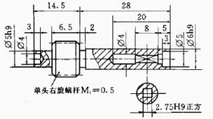
Figure 1 Speed Odometer Spindle Parts Drawing
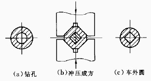
figure 2 Blind hole press molding method
The method has the advantages of simple process steps, convenient mold manufacturing and short production cycle. The disadvantage is that the workpiece axial direction is unconstrained free state during stamping, so the spindle is prone to bending deformation under the action of the pressing force. It is difficult to ensure the coaxiality between the square hole and the outer circle. At the same time, the mandrel is easily broken, and it is difficult to take out, and the labor intensity of the worker is large. In addition, after the external part of the workpiece is deformed, it is inconvenient for the outer circle of the finished machine. The practical square core rod is made of white steel knife material and directly made by wire cutting, so that it has good strength. In order to facilitate the core pulling rod, a slope of 1:100 is made in the longitudinal direction. At the same time, it is required to pay attention to lubrication at any time during stamping, and use a special tool to extract the core rod. The method has a genuine rate of less than 85% and is only suitable for small batch production.
II. Roll forming method
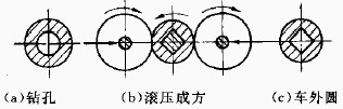
Figure 3 square hole rolling forming method
The method has the advantages that the workpiece is not unloaded, and all the steps are completed on the lathe, so that the square hole after molding can maintain a high coaxiality with the outer circle, and the quality is easy to ensure. And the equipment requirements are low, just ordinary lathes, especially suitable for small businesses. The disadvantage is that the radial force is large when rolling, which causes the workpiece to generate heat and cause vibration. In addition, the technical requirements for the workers are high. In practice, in order to overcome the problem of large radial force, a method of simultaneously feeding the front and rear double rollers is adopted, and hydraulic transmission is used. The radial forces are substantially canceled each other, and the rolling speed is also accelerated, and the effect is good. However, this method makes the feeding mechanism of the tool holder more complicated, and is often used when the batch size is large. The key to the success of this process is the mastery of rolling speed and feed rate. Not only should it be rolled into place, the square hole shape is full, and it should not be excessive, so as not to lose the margin of the outer circle finishing. Specific parameters such as the outer diameter of the blank before rolling, the rolling speed, the rolling feed amount, etc. can be obtained by a process test.
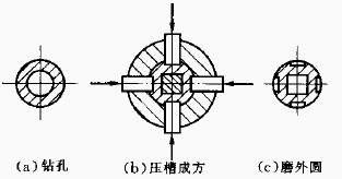
Figure 4 Mold molding method
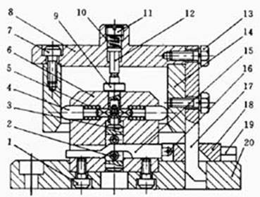
Figure 5 Square hole forming mold
1, 7, 13. Connecting screws
2. Wheel
3. Square core
4. Forming punch 5,
10. Reset spring
6. Concave body
8. Upper template
9. Workpiece
11. Adjustment screw
12. Upper ejector
14. Ring wedge
15 moving cam
16. Pin
17. Wedge
18. Slider
19. Guide rail
20. Mold base
The advantage of the method is that after the outer circle of the workpiece passes through the finishing car, the positioning precision in the mold is high, and the actual wall thickness is reduced, so that the deformation is easy, and thus the high quality can be obtained. Since the amount of embossing is small (single side 0.6 mm) and is performed in a localized range, the pressing force acting on the workpiece is relatively small. Therefore, the workpiece deformation after stamping is also small, and can directly enter the next grinding process, so that the productivity is greatly improved. In addition, the method is very convenient and labor-saving, and is popular among workers. The disadvantage is that after the molding, four longitudinal grooves with a width of 2 mm and a depth of 0.6 mm are left on the outer surface of the workpiece, and cannot be removed after grinding. Obviously, this does not meet the drawing requirements. In this regard, we think so: Since the groove is theoretically disadvantageous for the next grinding process, in practice, since the groove is localized, the effect is not large and the effect on use is smaller. Practice has proved that it helps to lubricate, because the tank is just used to store a certain amount of lubricating oil. So we made the appropriate modifications to the drawings to allow these grooves to exist. If you must eliminate these grooves to fully meet the drawing requirements, you can use the method of increasing the outer diameter of the blank and turning it after molding, but we recommend not to do so.
Figure 1 Speed Odometer Spindle Parts Drawing
Since the hole is a blind hole and the diameter is small, the undercut cannot be prefabricated and the chip removal is difficult, so conventional chip processing methods such as cutting and punching cannot be used. Therefore, we consider using the bottom hole first and then applying radial pressure to the shaft. It is plastically deformed so that it is formed by a round and square chipless molding process. Based on the above ideas, we have conceived and practiced a variety of pressure forming methods. The following are several methods for square hole forming.
I. Stamping forming method
The process steps are:
The roughing of the f6mm section of the rough car is f7.2mm, and the inner hole of the drill is f4mm deep and 20mm. Remove the workpiece and insert a 2.75mm square mandrel into the hole. After finding the correct orientation, the V-shaped mold with the upper and lower molds is 90 degrees on the punching machine, and the inner and outer sides are squared, the length is 8mm, and then the core rod is taken out (Fig. 2).
figure 2 Blind hole press molding method
The method has the advantages of simple process steps, convenient mold manufacturing and short production cycle. The disadvantage is that the workpiece axial direction is unconstrained free state during stamping, so the spindle is prone to bending deformation under the action of the pressing force. It is difficult to ensure the coaxiality between the square hole and the outer circle. At the same time, the mandrel is easily broken, and it is difficult to take out, and the labor intensity of the worker is large. In addition, after the external part of the workpiece is deformed, it is inconvenient for the outer circle of the finished machine. The practical square core rod is made of white steel knife material and directly made by wire cutting, so that it has good strength. In order to facilitate the core pulling rod, a slope of 1:100 is made in the longitudinal direction. At the same time, it is required to pay attention to lubrication at any time during stamping, and use a special tool to extract the core rod. The method has a genuine rate of less than 85% and is only suitable for small batch production.
II. Roll forming method
Process steps: Rough car f6mm segment outer circle to f7.2mm, The inner hole of the drill is f4mm deep and 20mm. The hole is f5mm deep and 3mm. Without unloading the workpiece, a 2.75mm square mandrel is clamped on the special live top of the lathe tailstock, and it is inserted into the hole and positioned with the f5mm hole. Then, the lathe is started, and the square core segment is pressed by a roller to deform the shrinkage hole and form a square hole under the constraint of the square core. After rolling in place, stop and take out the mandrel (Figure 3).
Figure 3 square hole rolling forming method
III. Mold forming method
In order to meet the needs of mass production, we have developed special molds to greatly increase productivity.
The process steps are:
After rough turning on the lathe, the outer circle of the f6mm section is refined and the grinding allowance is left. The inner hole of the drill is f4mm deep and 20mm, and the hole is f5mm deep and 3mm deep, which is used as a positioning reference. Custom stamping dies are then used on the stamping equipment. Four grooves are pressed at the corresponding diameter of the square hole section to transfer the material into the hole. A square hole is formed under the joint action of the mandrel, and the specific molding process is as shown in FIG. The special molding die is shown in Figure 5.
Figure 4 Mold molding method
The working condition of the mold is like this:
The workpiece 9 is placed in the concave mold body 6 by the outer circumference of the finished vehicle. When the punching machine drives the upper die plate 8 down, the workpiece is first pressed by the upper jack 12 on the positioning surface. The wedge 17 pushes the slider 18 to the left along the horizontal rail 19, and the moving cam 15 is driven by the pin 16 to move leftward. The cam ramp cooperates with the roller 2 to force the square core 3 to move upward into the inner bore of the workpiece and center the hole by the f5 mm hole. The upper template continues to move downward. At this time, the wedge column is in an idle stroke, and the upper ejector pin is kept in a tight state under the action of the spring 10, so that the workpiece is reliably positioned. Thereafter, the ring wedge 14 begins to enter the working stroke, and the four forming punches 4 are urged to move together in a centripetal direction, and the groove is pressed out on the workpiece to form a convex shape in the hole. The square hole is shaped by the joint action of the square core. On the return stroke, the upper die plate is advanced, and the ring wedge 14 first disengages the forming punch, so that the latter returns to the original position under the action of the return spring 5. The wedge 17 then pushes the slider 18 to the right, correspondingly moving the cam to the right, and the square core exits the inner hole through the ramp and the roller. Finally, the upper ejector 12 releases the workpiece, and the workpiece can be taken out, thus completing a work cycle.
The workpiece 9 is placed in the concave mold body 6 by the outer circumference of the finished vehicle. When the punching machine drives the upper die plate 8 down, the workpiece is first pressed by the upper jack 12 on the positioning surface. The wedge 17 pushes the slider 18 to the left along the horizontal rail 19, and the moving cam 15 is driven by the pin 16 to move leftward. The cam ramp cooperates with the roller 2 to force the square core 3 to move upward into the inner bore of the workpiece and center the hole by the f5 mm hole. The upper template continues to move downward. At this time, the wedge column is in an idle stroke, and the upper ejector pin is kept in a tight state under the action of the spring 10, so that the workpiece is reliably positioned. Thereafter, the ring wedge 14 begins to enter the working stroke, and the four forming punches 4 are urged to move together in a centripetal direction, and the groove is pressed out on the workpiece to form a convex shape in the hole. The square hole is shaped by the joint action of the square core. On the return stroke, the upper die plate is advanced, and the ring wedge 14 first disengages the forming punch, so that the latter returns to the original position under the action of the return spring 5. The wedge 17 then pushes the slider 18 to the right, correspondingly moving the cam to the right, and the square core exits the inner hole through the ramp and the roller. Finally, the upper ejector 12 releases the workpiece, and the workpiece can be taken out, thus completing a work cycle.
Figure 5 Square hole forming mold
1, 7, 13. Connecting screws
2. Wheel
3. Square core
4. Forming punch 5,
10. Reset spring
6. Concave body
8. Upper template
9. Workpiece
11. Adjustment screw
12. Upper ejector
14. Ring wedge
15 moving cam
16. Pin
17. Wedge
18. Slider
19. Guide rail
20. Mold base


