Pentagram 3D Modeling and CNC Machining
This design mainly introduces the overview of CNC machining technology, the cutting basis of CNC machining, the design of CNC machining technology, and the CNC machining process documentation, CNC machining tool systems, CNC machining fixtures, CNC machining processes for complex-shaped parts, CNC turning and machining center machining process.
Keywords: programming, process analysis, CNC machining
Five-pointed star three-dimensional modeling
1. Drawing of Pentagon.
Click the button on the curve generation toolbar to enter the space curve drawing state. In the immediate menu below the feature tree, select the circle method "Center Point_Radius" and follow the prompts to click the coordinate system origin, or press the Enter key. In the dialog box that pops up, enter the coordinates of the center point (0,0,0), radius R=100 and confirm, and then click the right mouse button to end the drawing of the circle.
Note: When inputting the coordinates of the point, it should be input under the status of English input method. Otherwise it will result in an error.
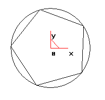
2. Draw a pentagon.
Click the button on the curve generation toolbar, select "Center" positioning in the immediate menu below the feature tree, and confirm the number of edges by 5 and connect them internally. Follow the system prompts to take the center point. The inward radius is 100 (the input method is the same as the circle drawing). Then right-click to end the drawing of the pentagon. So we got the five-pointed star corner. As shown below
5. Pentagram surface generation
(1). Generate surfaces from ruled faces.
Take a corner of a pentagram as an example. Click the ruled surface button on the surface toolbar and click the "curve + curve" option in the immediate menu below the feature tree to generate a ruled surface. Then use the left mouse button to pick up two lines that are adjacent to the corner to complete the surface.
(2). Generates a surface for the other corners.
When generating other surfaces, we can use the ruled surface to generate the surfaces one by one, or we can use the array function to perform a circular array of surfaces with one corner to realize the surface composition of the five-pointed star. Click the button in the geometric transformation toolbar and select the "Circular" array mode from the immediate menu under the feature tree. The distribution pattern is "uniform distribution" and the number of copies is "5". Use the left mouse button to pick up two surfaces on a corner and click the right mouse button to confirm. Then according to the prompt input center point coordinates (0,0,0), you can also use the mouse to pick up the coordinate origin, the system will automatically generate the surface of each corner. As shown below.
Note: When picking up adjacent lines, the pick-up position of the mouse should be as consistent as possible (corresponding position) so that the correct ruled surface can be obtained.
Note: When using a circular array, be sure to pay attention to the selection of the array plane, otherwise the array will have an array error. Therefore, before using the array in this example, it is best to press the “F5” shortcut key to confirm that the array plane is the XOY plane.
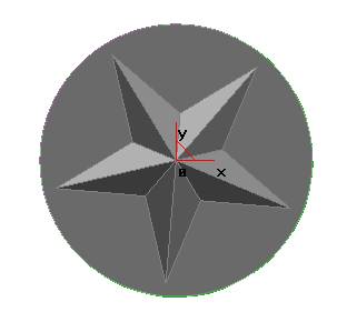
(3). Creates a five-pointed star's machining outline plane.
The circle is centered on the origin and its radius is 110. Use the mouse to click the Plane tool button in the Surface toolbar and select Clipping Plane from the Immediate menu below the feature tree. Pick the outline of the plane with the mouse, and then determine the chain search direction (pointer with the mouse), the system will prompt picking the first inner contour, Use a mouse to pick up a line on the bottom side of the star and click the right mouse button to confirm. Finish the contour plane. As shown below.
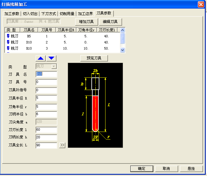
2. Set finishing "mill cutter parameters". As shown in the figure below
3. According to the system prompts to pick up the entire part surface as a machining surface, press the right button to confirm. The system prompts "Pick up the interference surface." If the part does not have an interference surface, press the right button to confirm skipping. The system will continue to prompt "Pick up the contour", pick up the outline of the part directly with the mouse, right-click to confirm, and then select and determine the chain search direction.
4. Generate finishing tracks. As shown below.
Note: The machining allowance for finishing = 0.
5, processing simulation, tool path inspection and modification
(1) Press “Visible” ammonium to display all generated rough/finish machining tracks.
(2) Click [Application] - [Trajectory Simulation] and select the option in the Immediate Menu as shown in the figure; According to the system prompts to pick up roughing tool trajectory and finishing trajectory, press the right key; The system will perform simulation processing.
as the picture shows.
6 . Observe the simulation machining pass route, test to determine whether the correct tool path, and reasonable (with or without over-cutting and other errors).
7. Click [Application] - [Track Edit] to pop up the "Track Edit" table. Follow the prompts to pick up the corresponding machining track or corresponding track point, modify the corresponding parameters, and modify the local track. If the modification is too large, the machining trajectory should be regenerated.
8. After the simulation test is correct, the rough/finish machining track can be saved.
Third, generate G code
1. Click [Application] - [Post Processing] - [Generate G Code],
In the pop-up "Select After File" dialog box, give the generated NC code file name (Pentagram. Cut) and its storage path, and press "OK" to exit.
2. Pick up the roughing trajectory and finishing trajectory respectively, press the right key to determine, and generate the processing G code.
Pentagram processing procedures are as follows:
(6,2008.11.17,16:35:36.8)
G90G54G00Z50.000
S3000M03
X0.000Y0.000Z50.000
X-115.000Y115.000
Z30.000
G01Z20.000F100
X115.000F1000
Y110.000F800
X-115.000F1000
Y105.000F800
X115.000F1000
Y100.000F800
X-115.000F1000
Y95.000F800
X115.000F1000
Y90.000F800
X-115.000F1000
Y85.000F800
X115.000F1000
Y80.000F800
X-115.000F1000
Y75.000F800
X115.000F1000
Y70.000F800
X-115.000F1000
Y65.000F800
X115.000F1000
Keywords: programming, process analysis, CNC machining
Five-pointed star three-dimensional modeling
1. Drawing of Pentagon.
Click the button on the curve generation toolbar to enter the space curve drawing state. In the immediate menu below the feature tree, select the circle method "Center Point_Radius" and follow the prompts to click the coordinate system origin, or press the Enter key. In the dialog box that pops up, enter the coordinates of the center point (0,0,0), radius R=100 and confirm, and then click the right mouse button to end the drawing of the circle.
Note: When inputting the coordinates of the point, it should be input under the status of English input method. Otherwise it will result in an error.
2. Draw a pentagon.
Click the button on the curve generation toolbar, select "Center" positioning in the immediate menu below the feature tree, and confirm the number of edges by 5 and connect them internally. Follow the system prompts to take the center point. The inward radius is 100 (the input method is the same as the circle drawing). Then right-click to end the drawing of the pentagon. So we got the five-pointed star corner. As shown below
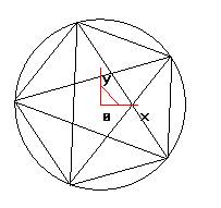
3. Five-pointed star configuration of the contour lines.
Through the above operations we have obtained the five corners of the five-pointed star, using the straight line button on the curve generation toolbar. In the immediate menu under the feature tree, select "two-point line", "continuous", and "non-orthogonal" (as shown in the figure) to connect the corners of the five-pointed star. As shown below.
Through the above operations we have obtained the five corners of the five-pointed star, using the straight line button on the curve generation toolbar. In the immediate menu under the feature tree, select "two-point line", "continuous", and "non-orthogonal" (as shown in the figure) to connect the corners of the five-pointed star. As shown below.
Use the "delete" tool to delete the extra line segment, click the button, and click the button to take the extra line segment. The picked line segment will turn red, and click the right button to confirm.
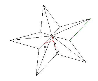
4. The space frame of the pentagram is constructed.
When constructing the space wireframe, we also need a vertex of the five-pointed star, so we need to find a point (0, 0, 20) in the height direction of the pentagram so that the five-pointed star's space wireframe construction can be achieved through two points.
Using the straight line button on the curve generation toolbar, select "Two-point line", "Continuous", and "Non-orthogonal" from the immediate menu below the feature tree, and use the mouse to click on a corner point of the five-pointed star.
Then click Enter and enter the vertex coordinates (0, 0, 20),
In the same way, the connection between the vertices and vertices of the five-pointed star will complete the five-pointed star's space wire frame.
As shown below.
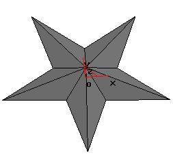
5. Pentagram surface generation
(1). Generate surfaces from ruled faces.
Take a corner of a pentagram as an example. Click the ruled surface button on the surface toolbar and click the "curve + curve" option in the immediate menu below the feature tree to generate a ruled surface. Then use the left mouse button to pick up two lines that are adjacent to the corner to complete the surface.
(2). Generates a surface for the other corners.
When generating other surfaces, we can use the ruled surface to generate the surfaces one by one, or we can use the array function to perform a circular array of surfaces with one corner to realize the surface composition of the five-pointed star. Click the button in the geometric transformation toolbar and select the "Circular" array mode from the immediate menu under the feature tree. The distribution pattern is "uniform distribution" and the number of copies is "5". Use the left mouse button to pick up two surfaces on a corner and click the right mouse button to confirm. Then according to the prompt input center point coordinates (0,0,0), you can also use the mouse to pick up the coordinate origin, the system will automatically generate the surface of each corner. As shown below.
Note: When picking up adjacent lines, the pick-up position of the mouse should be as consistent as possible (corresponding position) so that the correct ruled surface can be obtained.
Note: When using a circular array, be sure to pay attention to the selection of the array plane, otherwise the array will have an array error. Therefore, before using the array in this example, it is best to press the “F5” shortcut key to confirm that the array plane is the XOY plane.
(3). Creates a five-pointed star's machining outline plane.
The circle is centered on the origin and its radius is 110. Use the mouse to click the Plane tool button in the Surface toolbar and select Clipping Plane from the Immediate menu below the feature tree. Pick the outline of the plane with the mouse, and then determine the chain search direction (pointer with the mouse), the system will prompt picking the first inner contour, Use a mouse to pick up a line on the bottom side of the star and click the right mouse button to confirm. Finish the contour plane. As shown below.
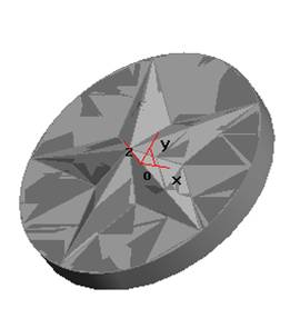
6. Generate processing entities
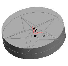
(1).Generate primitives. Select the XOY plane in the feature tree and click the right mouse button to select Create Sketch, as shown in the figure. Or simply click the Create Sketch button (press shortcut F2) to enter the sketching state.
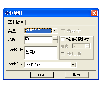
Click the Curve Projection button on the Curve Generation toolbar, use the mouse to pick up the existing outline circle, and project the circle onto the sketch as shown. Click the Extend Feed button on the Features toolbar and select the appropriate option in the Extrusion dialog box as shown. Click OK to finish.
(2). Cut out the material using curved surfaces, generating entity.
Click the Cursor Cut button on the Feature Toolbar, pick each existing surface with the mouse, and select the material removal direction. As shown in the figure, click OK to finish.
(3). Hide the surface with the Hide feature. Click and select [Edit] - [Hide], Use the mouse to select entities from right to left (single surface picked up with the mouse), right-click to confirm, Physical songs are hidden. as the picture shows.
(1).Generate primitives. Select the XOY plane in the feature tree and click the right mouse button to select Create Sketch, as shown in the figure. Or simply click the Create Sketch button (press shortcut F2) to enter the sketching state.
Click the Curve Projection button on the Curve Generation toolbar, use the mouse to pick up the existing outline circle, and project the circle onto the sketch as shown. Click the Extend Feed button on the Features toolbar and select the appropriate option in the Extrusion dialog box as shown. Click OK to finish.
(2). Cut out the material using curved surfaces, generating entity.
Click the Cursor Cut button on the Feature Toolbar, pick each existing surface with the mouse, and select the material removal direction. As shown in the figure, click OK to finish.
(3). Hide the surface with the Hide feature. Click and select [Edit] - [Hide], Use the mouse to select entities from right to left (single surface picked up with the mouse), right-click to confirm, Physical songs are hidden. as the picture shows.
4.2 Pentastar's CNC Machining
First, roughing parameter settings
1. Set "Roughing parameters". Click [Application] - [Trajectory Generation] - [Contour Roughing]. In the pop-up "Roughing Parameters Table", set "Roughing Parameters" as shown in the figure.
![4.2 Pentastar's CNC Machining First, roughing parameter settings 1. Set "Roughing parameters". Click [Application] - [Trajectory Generation] - [Contour Roughing]. In the pop-up "Roughing Parameters Table", set "Roughing Parameters" as shown in the figure.](/uploads/180622/1-1P62212594BU.png)
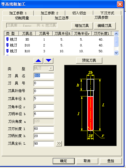
2. Set roughing "milling parameters". As shown in the figure below
3. Pick up the processing contour according to the system hint.
Pick up the rectangle that sets the processing area, then click the chain search arrow. According to the system prompts "Pick up the machined surface", select the entire surface of the entity, the system will turn all the picked up surfaces to red, and then press the right mouse button to end.
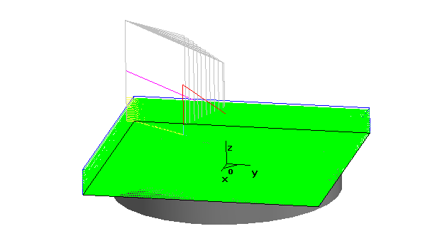
4. Generate roughing tool path.
Prompted: "Preparing surfaces please wait", "Surface treatment" and so on, then the system will automatically generate rough track.
The result is shown in the figure.
5. Hide the generated roughing trajectory.
Pick up trajectory. Right-click on the pop-up menu, select the [Hide] command, and hide the generated roughing track to facilitate the next step.
Second, Fine processing parameter setting
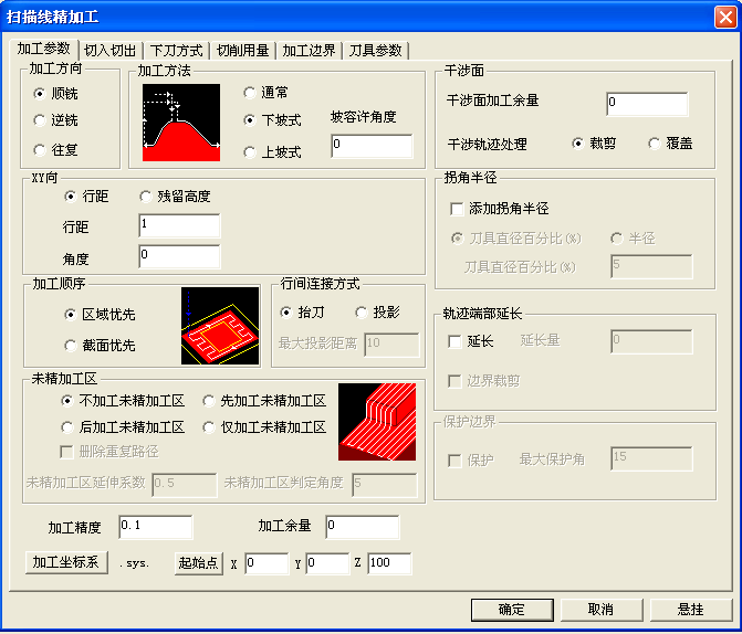
1. Set "finishing parameters". Click [Application] - [Trajectory Generation] - [Scan Line Finishing] to set the "finishing parameters" in the pop-up "finishing parameters table". As shown below.
First, roughing parameter settings
1. Set "Roughing parameters". Click [Application] - [Trajectory Generation] - [Contour Roughing]. In the pop-up "Roughing Parameters Table", set "Roughing Parameters" as shown in the figure.
2. Set roughing "milling parameters". As shown in the figure below
3. Pick up the processing contour according to the system hint.
Pick up the rectangle that sets the processing area, then click the chain search arrow. According to the system prompts "Pick up the machined surface", select the entire surface of the entity, the system will turn all the picked up surfaces to red, and then press the right mouse button to end.
4. Generate roughing tool path.
Prompted: "Preparing surfaces please wait", "Surface treatment" and so on, then the system will automatically generate rough track.
The result is shown in the figure.
5. Hide the generated roughing trajectory.
Pick up trajectory. Right-click on the pop-up menu, select the [Hide] command, and hide the generated roughing track to facilitate the next step.
Second, Fine processing parameter setting
1. Set "finishing parameters". Click [Application] - [Trajectory Generation] - [Scan Line Finishing] to set the "finishing parameters" in the pop-up "finishing parameters table". As shown below.
2. Set finishing "mill cutter parameters". As shown in the figure below
3. According to the system prompts to pick up the entire part surface as a machining surface, press the right button to confirm. The system prompts "Pick up the interference surface." If the part does not have an interference surface, press the right button to confirm skipping. The system will continue to prompt "Pick up the contour", pick up the outline of the part directly with the mouse, right-click to confirm, and then select and determine the chain search direction.
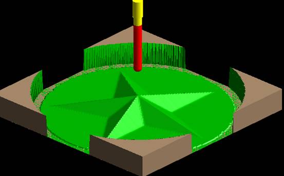
4. Generate finishing tracks. As shown below.
Note: The machining allowance for finishing = 0.
5, processing simulation, tool path inspection and modification
(1) Press “Visible” ammonium to display all generated rough/finish machining tracks.
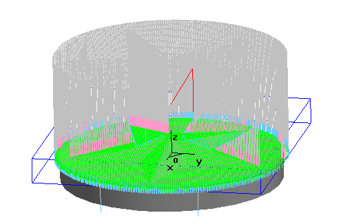
(2) Click [Application] - [Trajectory Simulation] and select the option in the Immediate Menu as shown in the figure; According to the system prompts to pick up roughing tool trajectory and finishing trajectory, press the right key; The system will perform simulation processing.
as the picture shows.
6 . Observe the simulation machining pass route, test to determine whether the correct tool path, and reasonable (with or without over-cutting and other errors).
7. Click [Application] - [Track Edit] to pop up the "Track Edit" table. Follow the prompts to pick up the corresponding machining track or corresponding track point, modify the corresponding parameters, and modify the local track. If the modification is too large, the machining trajectory should be regenerated.
8. After the simulation test is correct, the rough/finish machining track can be saved.
Third, generate G code
1. Click [Application] - [Post Processing] - [Generate G Code],
In the pop-up "Select After File" dialog box, give the generated NC code file name (Pentagram. Cut) and its storage path, and press "OK" to exit.
2. Pick up the roughing trajectory and finishing trajectory respectively, press the right key to determine, and generate the processing G code.
Pentagram processing procedures are as follows:
(6,2008.11.17,16:35:36.8)
G90G54G00Z50.000
S3000M03
X0.000Y0.000Z50.000
X-115.000Y115.000
Z30.000
G01Z20.000F100
X115.000F1000
Y110.000F800
X-115.000F1000
Y105.000F800
X115.000F1000
Y100.000F800
X-115.000F1000
Y95.000F800
X115.000F1000
Y90.000F800
X-115.000F1000
Y85.000F800
X115.000F1000
Y80.000F800
X-115.000F1000
Y75.000F800
X115.000F1000
Y70.000F800
X-115.000F1000
Y65.000F800
X115.000F1000


