Multipurpose Shaft CNC Lathe Processing Technology Design
Summary: Multipurpose shaft parts are designed, This shaft has a circular arc, process retreating slot, Thread retreating slot, a thread, a taper thread, an inner hole, and an inner arc. The material is 45 steel. For this multi-axis design, the "rough turning-finish turning" turning method will be used. Namely, the two end faces, the outer circle, the thread, the outer cone, the grooves, the arc and the drill holes are respectively divided into seven steps for rough machining and finishing.
This design mainly deals with the analysis of CNC machining processes and the processing of specific parts drawings. First of all, a brief introduction to the NC machining technology was carried out, and then the NC machining analysis was performed according to the parts drawing.
First, According to the machining process, cutting amount and other relevant factors of the part material, the tool, the handle and the contour characteristics of the parts are used to determine that 5 tools are required.
Secondly, program the part drawing graphics. This part is a multi-axis, the outer contour is composed of a straight line, an undercut, an arc, and a thread. Inside the left end of the part, a tapered hole and an inner arc are drilled. In the machining process, the workpiece needs to drill and then turn the inner arc.
third, When drill hole tool setting, it is necessary to refer back to the reference point first. The position of the tool is used to correct this, so that the tool position and the tool change point coincide to determine the programming coordinate system and programming origin, The NC machining program was compiled. Finally, the simulation and processing of the shaft parts were performed with programming simulation software.
Keywords: CNC programming, machining plan, cutting amount, machining program
1.1 Parts Drawing Process Analysis
as the picture shows:
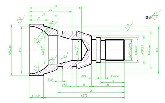
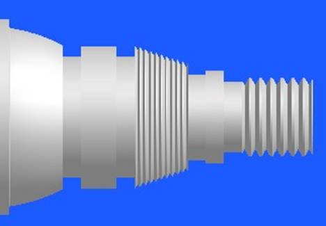
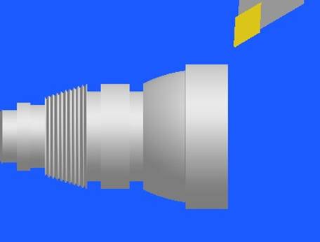
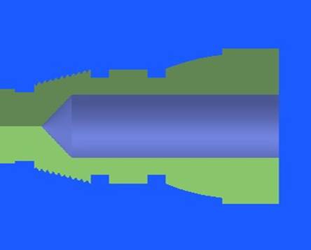
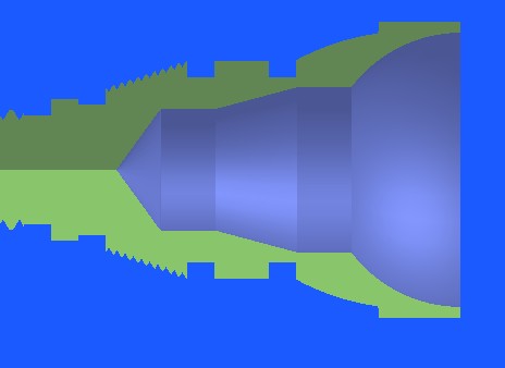
Part structure analysis:
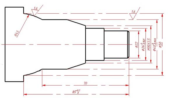
From the diagram, we can see that this part is made up of cylindrical surface, inner hole, inner cone surface, circular arc surface, groove, thread and so on. The shape of the contour of the turning part of the part turning is more complex and requires two-end machining. The machining accuracy and surface quality of the parts are very high. The important radial machining parts of the part are Ф54-0.039 0mm cylindrical sections (surface roughness Rɑ=1.6μm). R45 is connected to a circular arc, Ф40-0.033 0 cylindrical section, Ф22 + 0.021 0 and the radius of the inner bore of the inner bore of R25. The parts meet the requirements for the dimensioning of the NC machining, and the outline description is clear and complete. The part material is No.45 steel and the blank is ф60mm*110mm.
1.2 Analysis of Parts Technical Requirements
Low-Volume Manufacturing condition programming, It is not allowed to modify the plane with emery cloth and trowel. This is a requirement for high precision of planes. Unspecified tolerances, according to GB1804-M, heat treatment, quenched and tempered, HRC25-35, does not indicate the roughness part, the finish is Ra6.3, the embryo size is mm60mm*110mm.
1.3 Analysis of Parts Blanks and Materials
(1) Analysis of materials
In machining of this shaft part, the cutting force between the tool and the workpiece is large. The machinability, strength, hardness, plasticity, cold cutting, and mechanical properties of the workpiece material are all related to the material of the workpiece. Therefore, 45 steel was selected as the material for the shaft. The chemical composition of 45 steel contains C0.42% to 0.50%, Si0.17% to 0.37%, Mn0.50 to 0.80%, P≤0.035%, S≤0.035%, Cr≤0.25%, and N≤0.25%. Cu≤0.25%. Hardness requirements for 45 steel when cold working, hot rolled steel, indentation diameter not less than 3.9, Brinell hardness not less than 241HB, annealed steel indentation diameter not less than 4.4, Brinell hardness not less than 187HB, 45 steel mechanical properties: δs ≥ 335Mpa, δb ≥ 600Mpa, ∮ ≥ 40%, Ak ≥ 47J. 45 steel relatively machined carbide tool 1.0, high speed steel tool 1.0, 45 steel economic reasonable tooling requirements are also reasonable, 45 steel is widely used, mainly for the manufacture of steam turbines, compressors, pump parts manufacturing gears, shaft piston pin and other parts. According to the above data, it is suitable for machining of this shaft.
(2) Analysis of blanks
The blanks of shaft parts include bar stock, forgings and castings. Forgings: Suitable for parts with high strength and simple shapes. Large-size parts due to equipment restrictions, it is generally used open-die forging; Medium and small parts optional die forging; Rigid parts with complex shapes are not suitable for free forging and are suitable for blanks with complex shapes. Forged blanks of steel parts have higher mechanical properties than steel bars and steel castings. According to the structural shape and the outer contour size of the shaft part, forgings are used. The blank of this part should adopt forging, sawing by bar, and forging blank to Φ60X110mm, After forging the steel to obtain a uniform fibrous structure, improve its mechanical properties, but also increase the proportion of parts and blanks, reducing material consumption.
2.4 Selection of Parts Processing Equipment
2.4.1 Types of Machine Tools
The CNC lathe can automatically complete the machining of the inner and outer cylindrical surfaces, conical surfaces, arc surfaces, etc., on rotary parts such as shafts or discs, and can perform operations such as grooving, drilling, and expansion. According to the technical requirements of the parts, economical CNC lathes can be selected, and semi-closed loop servo systems in the form of stepping motors are generally used. These lathes are simple in structure and relatively low in price. This type of lathe is equipped with a three-jaw self-centering chuck, an ordinary tailstock or a numerically controlled hydraulic tailstock, which is suitable for turning longer shaft parts. The horizontal CNC lathe is selected according to the requirements of the spindle configuration. CNC lathes have high machining accuracy, can perform linear and circular interpolation, CNC lathes have good rigidity, high precision in manufacturing and tool setting, and can be manually and accurately compensated manually and automatically, and parts with high dimensional accuracy requirements can be machined. It can process particularly difficult surfaces and sizes with difficult-to-control slewing bodies with contour shapes, and it can easily turn the tapered surface of the taper and the inner and outer cylindrical threads to maintain the machining accuracy and improve the production efficiency. So it is very favorable for processing.
According to the structure, specification, and accuracy of the multi-axis components, selecting a turning center will result in a certain functional waste, so the economical CNC lathe is chosen, so the SSCK20/500 CNC lathe is selected.
2.4.2 Machine Tool Accuracy
The commonly used metals except for the quenched steels with machining accuracy of IT7 to IT8 and Ra 0.8 to Ra 1.6 μm can be finished by two steps of roughing and finishing. Processing precision of IT5 ~ IT6 grade, Ra0.2 ~ Ra 0.63μm in addition to the commonly used metal quenched steel, precision CNC lathes can be used, roughing → semi-finishing → fine car → fine car program processing. Machining precision is higher than that of commonly used metals other than quenched steels such as IT5 and Ra < 0.08μm, precision CNC lathes can be used, and machining can be carried out according to roughing, semi-finishing, finishing, precision turning. For hard-to-turn materials such as hardened steel, the method of roughing and semi-finishing can be used before quenching, and grinding is performed after quenching. Therefore, according to the requirements of the parts drawing, the accuracy of the SSCK20/500 CNC lathe is suitable for the accuracy of the multi-axis.
Main technical parameters of SSCK20/500 CNC lathe
2.5 Determining the Positioning and Fixture Scheme of the Workpiece
2.5.1 Determine the clamping scheme
Use the three jaw self centering chuck to clamp the rough outer circle of the parts, and determine the parts to extend the proper length (the limit distance of the machine tool should be taken into account). Parts need to be machined at both ends, so the position of the two clamping should be considered, taking into account that the steps on the left side of the 54mmx15mm can be used for clamping. Therefore, the right end is processed first, then the thread head of M22 Ph3P1.5 is clamped, and the inner arc of the 54mmx15mm step, the 22 inner hole and the R25 are machined.
2.5.2 Positioning Reference
The positioning and reference of the workpiece should be consistent with the design basis, and over-positioning should be prevented. It is best to choose "one side and two pins" as the positioning datum for the workpiece with the box, and the positioning datum should be carefully located on the numerical control machine tool. The workpiece is a solid shaft with a 30-degree taper bore at the end. Because the length of the shaft is not very long, the right end face of the workpiece and the outer circle of 48 are used as the reference for positioning. Use an ordinary three-jaw chuck to clamp the workpiece. Take the center of the right end face of the workpiece as the origin of the workpiece coordinates. The tool point is at (100.100). Since the entire surface of the part needs to be machined, the outer circle and one end face should be used as the rough reference, and then the processing should be performed through the principle of mutual reference. Follow the principle of "baseline coincidence." Select the outer surface of the left side of the blank when machining the right end, and select the surface of the right outer circle when processing the left side, so as to show that the positioning datum is the center line of the shaft.
2.6 Selection of Cutting Tools and Cutting Capacity
2.6.1 Tool Selection
The processing of this part,
(1) For rough and fine turning of the outer and flat ends, the 35 degree cemented carbide left deviation cutter is adopted.
Choose order = prevent interference between accessory rake face and workpiece contour, the auxiliary deflection angle should not be too small. Choose Kr =35.
(2) Slot cutters,
(3) The screw thread is chosen with carbide 60 degree external thread turning tool, and the radius of the tip should be less than the minimum fillet radius of the outline, taking re=0.15 to 0.2mm.
(4) Machining the left hole with a 22mm drill
(5) Internal turning tool.
The choice of tool is one of the important contents in the numerical control process design. The rational choice of tool not only affects the machining efficiency of the machine tool, but also affects the machining quality. The choice of tool usually considers the machining capability, process content, and workpiece material of the machine tool.
Compared with the traditional turning method, CNC turning has a higher requirement for tools. It not only requires high precision, good rigidity, high durability, but also requires dimensional stability and easy installation and adjustment. This requires the use of new high-quality materials to manufacture CNC machining tools and optimize tool parameters.
The selected tool is shown in the figure below:
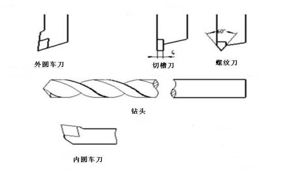
Cylindrical turning tools, grooved knives, thread knives, drill bits, internal turning tools.
2.6.2 Choice of cutting amount
The cutting amount includes spindle speed, cutting depth, and feed speed. For different processing methods, different cutting amounts need to be selected. The selection principle of the cutting amount is: to ensure the precision and surface roughness of the part, to give full play to the cutting performance of the tool and to ensure a reasonable tool life; And give full play to the performance of machine tools to maximize productivity and reduce costs.
(1) Determination of spindle speed
The spindle speed should be selected based on the allowable cutting speed and the workpiece (or tool) diameter. According to the processing requirements of parts, considering the workpiece material is 45 steel, The tool material is carbide steel, roughing speed 500r/min, finishing 1000r/min turning outer circle, Considering that the cutting force of fine thread is small, the thread is 400r/min. Because of the poor rigidity of the inner bore, the crude truck is used at 600 r/min, which is relatively easy to meet the processing requirements. The cutting knife is larger and 350 r/min is more secure.
(2) Selection of feed rate (feed rate) F (mm/r, mm/min)
The feed rate is an important parameter in the cutting amount of CNC machine tools. It is mainly selected according to the processing schedule and surface roughness requirements of the parts and the material properties of the tools and workpieces. Maximum feed rate, limited by machine stiffness and feed system performance. Generally, the roughing car uses a higher feed rate to remove the rough stock quickly. Finishing machining takes into consideration the principles of surface roughness and part accuracy. Roughing, since there is no requirement for high quality of the workpiece surface, At this time, the feed rate is selected based on factors such as the strength and rigidity of the machine tool feed mechanism, the strength and rigidity of the tool bar, the material of the tool, the dimensions of the tool shank and the workpiece, and the selected depth of cut. During finishing, the feed rate is selected based on surface roughness requirements, tool and workpiece material and other factors. Feed rate Vf can be calculated according to the formula Vf = f × n, where f represents the feed per revolution, generally take 0.3 ~ 0.8mm / r roughing; fine cars often take 0.1 ~ 0.3mm / r; Cut off often takes 0.05 ~ 0.2mm/r.
According to the above data to be selected a lower feed rate, obtained the following table:
(3) Determination of cutting depth
The depth of cut is determined by the stiffness of the machine, the workpiece and the tool. When the rigidity is allowed, the depth of cut should be equal to the machining allowance (excluding the finish turning amount) as much as possible, which can reduce the number of passes and increase the production efficiency. In order to ensure the quality of the machining surface, a small amount of finishing allowance may be left.
The selection of the cutting depth of the part based on the above data is roughly as follows:
In short, the specific value of the cutting amount should be determined by analogy based on machine tool performance, related manuals and practical experience. At the same time, the spindle speed, cutting depth and feed speed can be adapted to each other to form the optimal cutting amount. Cutting amount For different processing methods, different cutting amounts are required. Reasonable choice of cutting amount has a great influence on the surface quality, precision, and processing efficiency of parts.
Cutting amount selection method:
When roughing, you should try to ensure a high metal removal rate and the necessary tool life.
When finish turning, the requirements for machining accuracy and surface roughness are high, and the machining allowance is not large and uniform. Should focus on how to ensure the accuracy of processing, and on this basis, how to improve processing efficiency. Therefore, it is required to use smaller (but not too small) depth of cut and feed rate when finishing turning, and use high-performance tool materials and reasonable geometric parameters to increase the cutting speed as much as possible.
In summary, the processing sequence of this part is as follows:
2.7.1 Process I: Turn the right end surface, Turn blanks into 102mm bars

2.7.2 Process II: Roughing, finishing the outer contour of the right, to the desired size
2.7.4 Process IV Turn thread
2.7.5 Process V Turn the left end face to 100mm

2.7.6 Process VI Turning the left outer circle
2.7.7 Process VII Drilling
2.7.8 Process VIII Coarse and Fine Turning Inner Circle
2.10 Methods to Ensure Processing Accuracy
In order to ensure and improve the machining accuracy, according to the production process must be the main reason for the error, Take corresponding error prevention or error compensation and other effective technological approaches to directly control the influence of the original error on the part machining accuracy.
2.10.1 Selection of Tool Radius
(1). The tool radius R can not be machined when it is larger than the workpiece corner radius.
(2) When the tool is small, it cannot be machined with a large amount of cutting (difficult tool rigidity).
2.10.2 Use suitable cutting fluid
(1). Cutting fluid is mainly used to reduce friction during cutting and reduce cutting temperature. The rational use of cutting fluid plays an important role in improving the tool's durability, machining surface quality and machining accuracy.
(2). Non-water soluble cutting fluid: Cutting oil, solid lubricants, non-soluble cutting fluids mainly play a role in lubrication.
(3). Water-soluble cutting fluid: Aqueous solutions, emulsions, and water-soluble cutting fluids have good cooling and cleaning effects. Therefore, this design uses an aqueous solution for cooling.
This design mainly deals with the analysis of CNC machining processes and the processing of specific parts drawings. First of all, a brief introduction to the NC machining technology was carried out, and then the NC machining analysis was performed according to the parts drawing.
First, According to the machining process, cutting amount and other relevant factors of the part material, the tool, the handle and the contour characteristics of the parts are used to determine that 5 tools are required.
Secondly, program the part drawing graphics. This part is a multi-axis, the outer contour is composed of a straight line, an undercut, an arc, and a thread. Inside the left end of the part, a tapered hole and an inner arc are drilled. In the machining process, the workpiece needs to drill and then turn the inner arc.
third, When drill hole tool setting, it is necessary to refer back to the reference point first. The position of the tool is used to correct this, so that the tool position and the tool change point coincide to determine the programming coordinate system and programming origin, The NC machining program was compiled. Finally, the simulation and processing of the shaft parts were performed with programming simulation software.
Keywords: CNC programming, machining plan, cutting amount, machining program
Part processing technology analysis
as the picture shows:
Part structure analysis:
From the diagram, we can see that this part is made up of cylindrical surface, inner hole, inner cone surface, circular arc surface, groove, thread and so on. The shape of the contour of the turning part of the part turning is more complex and requires two-end machining. The machining accuracy and surface quality of the parts are very high. The important radial machining parts of the part are Ф54-0.039 0mm cylindrical sections (surface roughness Rɑ=1.6μm). R45 is connected to a circular arc, Ф40-0.033 0 cylindrical section, Ф22 + 0.021 0 and the radius of the inner bore of the inner bore of R25. The parts meet the requirements for the dimensioning of the NC machining, and the outline description is clear and complete. The part material is No.45 steel and the blank is ф60mm*110mm.
1.2 Analysis of Parts Technical Requirements
Low-Volume Manufacturing condition programming, It is not allowed to modify the plane with emery cloth and trowel. This is a requirement for high precision of planes. Unspecified tolerances, according to GB1804-M, heat treatment, quenched and tempered, HRC25-35, does not indicate the roughness part, the finish is Ra6.3, the embryo size is mm60mm*110mm.
1.3 Analysis of Parts Blanks and Materials
(1) Analysis of materials
In machining of this shaft part, the cutting force between the tool and the workpiece is large. The machinability, strength, hardness, plasticity, cold cutting, and mechanical properties of the workpiece material are all related to the material of the workpiece. Therefore, 45 steel was selected as the material for the shaft. The chemical composition of 45 steel contains C0.42% to 0.50%, Si0.17% to 0.37%, Mn0.50 to 0.80%, P≤0.035%, S≤0.035%, Cr≤0.25%, and N≤0.25%. Cu≤0.25%. Hardness requirements for 45 steel when cold working, hot rolled steel, indentation diameter not less than 3.9, Brinell hardness not less than 241HB, annealed steel indentation diameter not less than 4.4, Brinell hardness not less than 187HB, 45 steel mechanical properties: δs ≥ 335Mpa, δb ≥ 600Mpa, ∮ ≥ 40%, Ak ≥ 47J. 45 steel relatively machined carbide tool 1.0, high speed steel tool 1.0, 45 steel economic reasonable tooling requirements are also reasonable, 45 steel is widely used, mainly for the manufacture of steam turbines, compressors, pump parts manufacturing gears, shaft piston pin and other parts. According to the above data, it is suitable for machining of this shaft.
(2) Analysis of blanks
The blanks of shaft parts include bar stock, forgings and castings. Forgings: Suitable for parts with high strength and simple shapes. Large-size parts due to equipment restrictions, it is generally used open-die forging; Medium and small parts optional die forging; Rigid parts with complex shapes are not suitable for free forging and are suitable for blanks with complex shapes. Forged blanks of steel parts have higher mechanical properties than steel bars and steel castings. According to the structural shape and the outer contour size of the shaft part, forgings are used. The blank of this part should adopt forging, sawing by bar, and forging blank to Φ60X110mm, After forging the steel to obtain a uniform fibrous structure, improve its mechanical properties, but also increase the proportion of parts and blanks, reducing material consumption.
2.4 Selection of Parts Processing Equipment
2.4.1 Types of Machine Tools
The CNC lathe can automatically complete the machining of the inner and outer cylindrical surfaces, conical surfaces, arc surfaces, etc., on rotary parts such as shafts or discs, and can perform operations such as grooving, drilling, and expansion. According to the technical requirements of the parts, economical CNC lathes can be selected, and semi-closed loop servo systems in the form of stepping motors are generally used. These lathes are simple in structure and relatively low in price. This type of lathe is equipped with a three-jaw self-centering chuck, an ordinary tailstock or a numerically controlled hydraulic tailstock, which is suitable for turning longer shaft parts. The horizontal CNC lathe is selected according to the requirements of the spindle configuration. CNC lathes have high machining accuracy, can perform linear and circular interpolation, CNC lathes have good rigidity, high precision in manufacturing and tool setting, and can be manually and accurately compensated manually and automatically, and parts with high dimensional accuracy requirements can be machined. It can process particularly difficult surfaces and sizes with difficult-to-control slewing bodies with contour shapes, and it can easily turn the tapered surface of the taper and the inner and outer cylindrical threads to maintain the machining accuracy and improve the production efficiency. So it is very favorable for processing.
According to the structure, specification, and accuracy of the multi-axis components, selecting a turning center will result in a certain functional waste, so the economical CNC lathe is chosen, so the SSCK20/500 CNC lathe is selected.
2.4.2 Machine Tool Accuracy
The commonly used metals except for the quenched steels with machining accuracy of IT7 to IT8 and Ra 0.8 to Ra 1.6 μm can be finished by two steps of roughing and finishing. Processing precision of IT5 ~ IT6 grade, Ra0.2 ~ Ra 0.63μm in addition to the commonly used metal quenched steel, precision CNC lathes can be used, roughing → semi-finishing → fine car → fine car program processing. Machining precision is higher than that of commonly used metals other than quenched steels such as IT5 and Ra < 0.08μm, precision CNC lathes can be used, and machining can be carried out according to roughing, semi-finishing, finishing, precision turning. For hard-to-turn materials such as hardened steel, the method of roughing and semi-finishing can be used before quenching, and grinding is performed after quenching. Therefore, according to the requirements of the parts drawing, the accuracy of the SSCK20/500 CNC lathe is suitable for the accuracy of the multi-axis.
Main technical parameters of SSCK20/500 CNC lathe
| Maximum turning diameter machine | Ф400mm |
| Clamp diameter | Ф200mm |
| Maximum cutting diameter | Ф200mm |
| Maximum cutting length | 500mm |
| Spindle speed range | 24r/min~2400r/mm(Continuous stepless) |
| Spindle diameter | Ф55mm |
| Slip saddle maximum longitudinal travel | 550mm |
| Maximum lateral travel of skateboard | 200mm |
| Fast moving speed | X axis 6m/min;Z axis 12m/min |
| Turret station number | 6 Station |
| Tool specifications | turning tool 20mm×20mm |
| Tool hole diameter | Ф32mm |
| Tool selection mode | Clockwise direction |
| Minimum input equivalent | X axis (diameter)0.001mm;Z axis 0.001mm |
| Tail sleeve diameter | Ф70mm |
| Tailstock sleeve maximum stroke | 60mm |
| Top tapered hole | Mode 4 |
| Main motor power | Continuous load 11kw |
| Feed servo motor power | X axis AC0.6kw;Z axis AC0.6kw |
| Hydraulic station motor power | 1.1kw |
| Cutting fluid motor power | 0.0125kw |
| Machine dimensions (L × W × H) | 2600mm×12400mm×1715mm |
| Machine tool net quality | 2300kg |
2.5 Determining the Positioning and Fixture Scheme of the Workpiece
2.5.1 Determine the clamping scheme
Use the three jaw self centering chuck to clamp the rough outer circle of the parts, and determine the parts to extend the proper length (the limit distance of the machine tool should be taken into account). Parts need to be machined at both ends, so the position of the two clamping should be considered, taking into account that the steps on the left side of the 54mmx15mm can be used for clamping. Therefore, the right end is processed first, then the thread head of M22 Ph3P1.5 is clamped, and the inner arc of the 54mmx15mm step, the 22 inner hole and the R25 are machined.
2.5.2 Positioning Reference
The positioning and reference of the workpiece should be consistent with the design basis, and over-positioning should be prevented. It is best to choose "one side and two pins" as the positioning datum for the workpiece with the box, and the positioning datum should be carefully located on the numerical control machine tool. The workpiece is a solid shaft with a 30-degree taper bore at the end. Because the length of the shaft is not very long, the right end face of the workpiece and the outer circle of 48 are used as the reference for positioning. Use an ordinary three-jaw chuck to clamp the workpiece. Take the center of the right end face of the workpiece as the origin of the workpiece coordinates. The tool point is at (100.100). Since the entire surface of the part needs to be machined, the outer circle and one end face should be used as the rough reference, and then the processing should be performed through the principle of mutual reference. Follow the principle of "baseline coincidence." Select the outer surface of the left side of the blank when machining the right end, and select the surface of the right outer circle when processing the left side, so as to show that the positioning datum is the center line of the shaft.
2.6 Selection of Cutting Tools and Cutting Capacity
2.6.1 Tool Selection
The processing of this part,
(1) For rough and fine turning of the outer and flat ends, the 35 degree cemented carbide left deviation cutter is adopted.
Choose order = prevent interference between accessory rake face and workpiece contour, the auxiliary deflection angle should not be too small. Choose Kr =35.
(2) Slot cutters,
(3) The screw thread is chosen with carbide 60 degree external thread turning tool, and the radius of the tip should be less than the minimum fillet radius of the outline, taking re=0.15 to 0.2mm.
(4) Machining the left hole with a 22mm drill
(5) Internal turning tool.
The choice of tool is one of the important contents in the numerical control process design. The rational choice of tool not only affects the machining efficiency of the machine tool, but also affects the machining quality. The choice of tool usually considers the machining capability, process content, and workpiece material of the machine tool.
Compared with the traditional turning method, CNC turning has a higher requirement for tools. It not only requires high precision, good rigidity, high durability, but also requires dimensional stability and easy installation and adjustment. This requires the use of new high-quality materials to manufacture CNC machining tools and optimize tool parameters.
The selected tool is shown in the figure below:
Cylindrical turning tools, grooved knives, thread knives, drill bits, internal turning tools.
2.6.2 Choice of cutting amount
The cutting amount includes spindle speed, cutting depth, and feed speed. For different processing methods, different cutting amounts need to be selected. The selection principle of the cutting amount is: to ensure the precision and surface roughness of the part, to give full play to the cutting performance of the tool and to ensure a reasonable tool life; And give full play to the performance of machine tools to maximize productivity and reduce costs.
(1) Determination of spindle speed
The spindle speed should be selected based on the allowable cutting speed and the workpiece (or tool) diameter. According to the processing requirements of parts, considering the workpiece material is 45 steel, The tool material is carbide steel, roughing speed 500r/min, finishing 1000r/min turning outer circle, Considering that the cutting force of fine thread is small, the thread is 400r/min. Because of the poor rigidity of the inner bore, the crude truck is used at 600 r/min, which is relatively easy to meet the processing requirements. The cutting knife is larger and 350 r/min is more secure.
(2) Selection of feed rate (feed rate) F (mm/r, mm/min)
The feed rate is an important parameter in the cutting amount of CNC machine tools. It is mainly selected according to the processing schedule and surface roughness requirements of the parts and the material properties of the tools and workpieces. Maximum feed rate, limited by machine stiffness and feed system performance. Generally, the roughing car uses a higher feed rate to remove the rough stock quickly. Finishing machining takes into consideration the principles of surface roughness and part accuracy. Roughing, since there is no requirement for high quality of the workpiece surface, At this time, the feed rate is selected based on factors such as the strength and rigidity of the machine tool feed mechanism, the strength and rigidity of the tool bar, the material of the tool, the dimensions of the tool shank and the workpiece, and the selected depth of cut. During finishing, the feed rate is selected based on surface roughness requirements, tool and workpiece material and other factors. Feed rate Vf can be calculated according to the formula Vf = f × n, where f represents the feed per revolution, generally take 0.3 ~ 0.8mm / r roughing; fine cars often take 0.1 ~ 0.3mm / r; Cut off often takes 0.05 ~ 0.2mm/r.
According to the above data to be selected a lower feed rate, obtained the following table:
| Rough | fine | |
| Foreign circle | 0.5mm/r | 0.2mm/r |
| Thread | 0.08mm/r | 0.03mm/r |
| Inner hole | 0.4mm/r | 0.2mm/r |
| groove | 0.1mm/r | |
(3) Determination of cutting depth
The depth of cut is determined by the stiffness of the machine, the workpiece and the tool. When the rigidity is allowed, the depth of cut should be equal to the machining allowance (excluding the finish turning amount) as much as possible, which can reduce the number of passes and increase the production efficiency. In order to ensure the quality of the machining surface, a small amount of finishing allowance may be left.
The selection of the cutting depth of the part based on the above data is roughly as follows:
| Rough | fine | |
| Foreign circle | 10(mm) | 0.2-0.5(mm) |
| Thread | 10(mm) | 0.1-0.5(mm) |
| Inner hole | With the number of feeds in turn decreased | |
| groove | According to knife width, it is performed twice | |
Cutting amount selection method:
When roughing, you should try to ensure a high metal removal rate and the necessary tool life.
When finish turning, the requirements for machining accuracy and surface roughness are high, and the machining allowance is not large and uniform. Should focus on how to ensure the accuracy of processing, and on this basis, how to improve processing efficiency. Therefore, it is required to use smaller (but not too small) depth of cut and feed rate when finishing turning, and use high-performance tool materials and reasonable geometric parameters to increase the cutting speed as much as possible.
In summary, the processing sequence of this part is as follows:
2.7.1 Process I: Turn the right end surface, Turn blanks into 102mm bars
2.7.2 Process II: Roughing, finishing the outer contour of the right, to the desired size
2.7.3 Process III Slotting
2.7.4 Process IV Turn thread
2.7.5 Process V Turn the left end face to 100mm
2.7.6 Process VI Turning the left outer circle
2.7.7 Process VII Drilling
2.7.8 Process VIII Coarse and Fine Turning Inner Circle
| CNC machining processes card | ||||||||||||||||||
| Part Name | Multi-axis | Part Number | Figure 2 | Fixture name | Three-jaw chuck | |||||||||||||
| Equipment name and model | CNC Lathe SSCK20/500 | |||||||||||||||||
| Material name and brand | 45 steel | Hardness | HRC68 | Process name | Machining cylindrical | employee ID | Ⅱ | |||||||||||
 |
||||||||||||||||||
|
Step number |
Step content | Cutting amount | Tools | Measuring tool | ||||||||||||||
| n(r/min) | f(mm/r) | ap(mm) | No. | name | name | |||||||||||||
| 1 | Rough turning outer circle | 500 | 0.5 | 10 | T0101 | Round turning tool | Vernier caliper | |||||||||||
| 2 | Fine turning outer circle | 1000 | 0.2 | 0.3 | T0101 | Round turning tool | micrometer | |||||||||||
| 3 | Chamfer | 500 | 0.14 | 1.5 | T0101 | Round turning tool | ||||||||||||
| 4 | Rough outer arc | 500 | 0.5 | 10 | T0101 | Round turning tool | Vernier caliper | |||||||||||
| 5 | Fine car outer arc | 1000 | 0.2 | 0.3 | T0101 | Round turning tool | micrometer | |||||||||||
2.10 Methods to Ensure Processing Accuracy
In order to ensure and improve the machining accuracy, according to the production process must be the main reason for the error, Take corresponding error prevention or error compensation and other effective technological approaches to directly control the influence of the original error on the part machining accuracy.
2.10.1 Selection of Tool Radius
(1). The tool radius R can not be machined when it is larger than the workpiece corner radius.
(2) When the tool is small, it cannot be machined with a large amount of cutting (difficult tool rigidity).
2.10.2 Use suitable cutting fluid
(1). Cutting fluid is mainly used to reduce friction during cutting and reduce cutting temperature. The rational use of cutting fluid plays an important role in improving the tool's durability, machining surface quality and machining accuracy.
(2). Non-water soluble cutting fluid: Cutting oil, solid lubricants, non-soluble cutting fluids mainly play a role in lubrication.
(3). Water-soluble cutting fluid: Aqueous solutions, emulsions, and water-soluble cutting fluids have good cooling and cleaning effects. Therefore, this design uses an aqueous solution for cooling.


