Machining Method of Groove of Fine Copper Tube Air Bearing
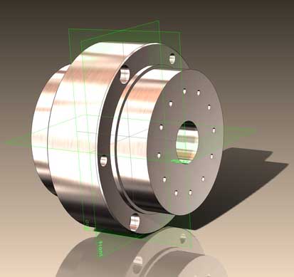
A pattern of herringbone shapes is formed on the air bearing. The resist thickness was approximately 10 microns, the scanning speed was maintained at 200 microns per second, and the laser exposure light power measured before the sample was 65 microwatts. The parallel 15 sets of spatial patterns are formed at an angle of plus or minus 60 degrees to the axis over the entire circumference of the tube. As shown in Fig. 5, the sample tubes were fixed at the center of the copper block to facilitate observation and measurement of patterns, and they were cut from the axial direction by a milling machine. The front view of the pattern can be viewed through an optical microscope and then the width of the pattern can be measured using a width measurement software calibrated by a measurement standard dial.
Figure 5. Method of observing the inside of the pipe
In past studies, the spiral pattern was fairly straightforward by continuously moving the sample tube at a constant rate. On the contrary, many discrete patterns need to be delineated for processing herringbone grooves. Once the discrete pattern appears, the exposure scanning should be turned off frequently. Then, if the table used to scan the sample exposure stops working, the laser will continue to expose the same point on the sample. For this reason, it is necessary to use the shutter to grasp the appropriate actual or start and pause in synchronization with the workbench to stop the exposure. If this is not the case, the space pattern will shrink into an ellipse or a match-like projection. As shown in Figure 6, when the exposure shutter is manually closed only after manually turning the table on and off before starting the table, the pattern will be overexposed and the actual shape will become like a match head. On the other hand, when the opening and closing of the shutter is automatically controlled, and the timing is also suitable, the resulting space pattern has a good shape without any protrusions, as shown in FIG. Since the cut tube sample is deformed in the front view of the tube side portion, as shown in Fig. 8, only the width of the intermediate portion of the space pattern can be evaluated. Figure 9 shows that the width of the pattern is uniform. The pattern has an average width of 24.8 microns and a deviation of 1.9 microns in three directions. The average and deviation values of other samples were calculated.
In addition, we evaluated the post-etched bearing grooves. The etching voltage was 5 volts and the etching time was 300 seconds. Since the tube sample that was cut open for observation was not used for etching, we processed other samples for this study. Figure 10 shows an image of an etched bearing groove. The edges of the groove pattern are smooth and of sufficient width, as shown in FIG. Then, a resist pattern having almost uniformity was obtained, and the average width was 28 μm, and the deviation in three directions was 2.7 μm. The mean and deviation values, including other samples, were calculated.
Micromachining of grooves on the inner surface of air bearing fine copper tubes
Image 6. Use manual shutter groove pattern to become match head shape
Figure 7. A herringbone-shaped bare pattern formed on the inner surface of a copper tube coated with a resist. When an automatic shutter is used and the timing of the switch is appropriate, the pattern becomes natural.
Figure 8. Schematic diagram of pattern width measurement points
Figure 9. Width distribution of bearing patterns generated on the inner surface of a copper tube coated with a resist coating
Figure 10. Herringbone bearing pattern formed on the inner surface of the etched copper tube
Figure 11. After etching the width of the bearing groove pattern of distribution
The difference in the average width of the resist coated and etched groove patterns was evaluated and the etch depth was approximately 1.6 microns. Accordingly, it can be assumed that the progress of the wet etching is isotropic, and the undercut on one side is almost equal to the depth. However, because the samples used for evaluation vary, their true depth, uniformity, and repeatability should be evaluated in detail in the future.
5. Applicability of air bearings
In order to verify that the tube samples with the herringbone grooves can be used as sleeves for air bearings, they are machined into sleeves and fixed to the shaft, as shown in FIG. The hollow shaft is inserted into the sleeve as a fixed axis, and then the shaft is suspended in the axial direction by means of a neodymium magnet. The air required for the air bearing enters the bearing through the hollow shaft and small holes. The rotation of the shaft is the rotation of the shaft driven by the air. As shown in Fig. 13, the number of passes through the shaft ribs was calculated using a photocoupler to measure the number of revolutions. As shown in Figure 14, the shaft can still rotate smoothly at a maximum speed of 21,000 rpm. It is believed that the additional fluctuations caused by the high rotational speed are caused by the manual control of the blown air and the shape error of the hand-made shaft. In contrast, when the air bearing has no grooves, a more dangerous slip phenomenon occurs, and the speed at which the air bearing is used is not achieved.
Therefore, this proves that the processed air bearing is very effective. The speed of the shaft depends on the weight of the shaft itself and the amount of driving force. In the future, if necessary, you can increase them to get higher speeds.
Although the air used in this bearing is supplied through a hollow shaft, in many cases the shaft is driven by a motor or other power. Therefore, any disturbance of the shaft caused by the air pipe and the air supply seal should be avoided.
Further, as shown in Fig. 15, if a static air is blown into a shallow groove having a suitable size through a small air blast hole, the air bearing is sufficient to support a large load. Since the groove is equivalent to an air bag during operation, the total contact area of the support shaft through the pressure is greatly increased, thereby greatly improving the supportability. Therefore, internal lithography must rely on high speed and small diameter shafts that carry slightly heavy loads.
Furthermore, in the case of a rotary air bearing that is subjected to loads in all directions, it is preferable to be uniformly supported by all directions. If there are many herringbone grooves on the air bearing, the shaft is supported by all the air in the annulus. Further, in the case of the herringbone bearing, since the groove constantly overlaps and is inclined with respect to the rotation direction, the supporting force does not fluctuate.
Figure 12. Manual rotor with air bearing bushing
Figure 13. Test for studying the performance of processed air bearings
Figure 14. Speed stability comparison of shafts with air bearing and airless bearing
Figure 15. The structure of the air bearing groove that can adapt to the upward heavy load of all parties. The herringbone groove should be placed as a static pressure bag
The sleeve or the outer annulus is on one side, not on the side of the shaft.
6. Conclusion
This paper studies the applicability of internal lithography in processing air bearings. The successfully formed herringbone grooves have no end projections and the pattern width is almost uniform. When the shaft equipped with the internal air bearing rotates around a hollow shaft that can be driven into the drive air, the shaft speed can reach up to 21,000 rpm without slippage. The results show that the combination of internal lithography and electrolytic etching is very effective for processing air bearings.


