Five-axis CNC production car sludge modeling details
Automotive stylists use computer-aided modeling techniques (CAS) and reverse engineering techniques (RE) to generate three-dimensional mathematical models. According to the mathematical model, the CNC machining personnel processed the corresponding sludge model for evaluation and modification. This paper uses the five-axis machining center provided by BACCI of Italy to process the car sludge model. The related technologies are summarized, and the mathematical model of the product, the selection of the tool, and the generation of the processing trajectory are discussed.
In the process of modern automobile development, the stylist can use the computer-aided modeling software to generate three-dimensional mathematical models, or use the existing physical objects to scan the data and transform the mathematical models from reverse engineering. Although computer technology can now simulate the display effect, the actual process is often verified and modified by the real physical model. In this process, using advanced CNC machining technology instead of traditional manual operation, accurate and efficient product development process can be realized.
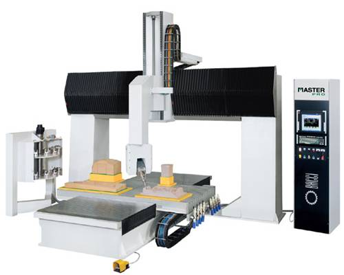
Five-axis machining center for automobile sludge making - Italy BACCI five-axis machining center. The equipment has CAD 3D drawing design and production functions, spatial surface profile milling, hollowing, punching, cutting, engraving and other functions. BACCI five-axis machining center can process automobile sludge modeling, building model, large commercial center model, bridge model, art model, etc. BACCI five-axis machining center has x, y, z and a, c five axes, specializing in space multi-dimensional machining, Hollow processing, can quickly process a variety of models, shapes, and processing surface finish is very high, saving time, labor.
The three-dimensional surface mathematical model is the basis for the milling of the sludge model. The outer surface of the car is composed of complex three-dimensional free-form surfaces, and most of them are trimmed surfaces, so the requirements for the three-dimensional mathematical model of the product are high. The mathematical requirements for automotive exterior surfaces generated by computer-aided modeling and reverse engineering software should generally meet the following basic requirements:
Since the outer surface of the car is a free-form surface, adjacent surfaces are connected by a transition surface, and most of the surfaces are trimmed surfaces. Therefore, it is not suitable to use the equal parameter method to generate the tool path, and the multi-curved equal-space continuous processing method.
(3) Tool selection
The ball-end milling cutter is selected by machining a free-form surface using a numerically controlled machine tool. Ball knives with diameters of 20mm, 10mm and 3mm are used in the machining process. In the roughing and matrix processing, a ball cutter with a larger diameter is used for the purpose of quickly removing excess material;
In finishing, the tool is selected according to the radius of curvature of the free surface. The specific principle is that the radius of the ball cutter is less than or equal to the minimum radius of curvature of the surface to be machined. Only in this way can the processed model truly reflect the shape of the mathematical model. In addition, in order to make the processing surface smooth and uniform, the depth of the knife and the speed of the knife should be reasonably determined.
4 The specific processing process of the sludge model on the outer surface of the car
The base processing of the sludge model refers to the processing of the foam material adhered to the wooden skeleton. The outer dimensions of the wooden frame are about 100 mm smaller than the mathematical model of the outer surface. The foam is applied to the frame, and the outer surface of the wooden skeleton is required to be filled with foam, and the foam and the foam and the foam and the wood are firmly adhered. In order to ensure the paste effect, it is processed 24 hours after the paste is finished. Due to the shape of the foam itself, the thickness of the paste cannot be uniform, and the surface of the paste can be properly trimmed with a hand saw to remove a significant portion.
The substrate processing trajectory is performed in two steps. The first step is to set the machining allowance to 0mm. The second step sets the machining allowance to minus 30mm. These two steps are to remove excess foam and leave a place for the paste mud.
With the above preparations, you are ready to process. The skeleton is bolted to the machining bracket, and the model is placed horizontally as far as possible, and the center line is substantially parallel to the machine X axis. Define the machining coordinate system, set the tool length, set the reference point, and use the machine's own related functions to generate the tool path for milling.
4.2 Roughing of the sludge model
After the base is processed, roughing can be prepared. This process includes paste mud, generating tool path and specific processing. Clean the foam crumbs on the substrate before the paste mud, so as not to affect the paste of the sludge;
Then, a long iron with a length of about 60 mm is pinned on the surface of the foam substrate to make a thickness reference, so that the tip of the nail is about 35 mm from the surface of the foam. Next, paste the oil on the foam base, pay attention to the thickness of the sludge is basically the same as the top of the nail, and the application is even. But don't cover the nails, remove all the nails after the paste, and repair the nail holes.
A tool path with a machining allowance of 5 mm is generated. After the tool path and the paste slurry are prepared, they can be processed. The coordinate system and reference point used for machining are the same as those for the base machining, but the tool length must be redefined after replacing the new tool.
4.3 Finishing of the sludge model
Finishing To achieve dimensional accuracy, the relevant processing parameters must be carefully determined. The size of the tool used is determined based on the radius of curvature of the mathematical model of the outer surface. In the model processing, the tools of Ф10mm and Ф3mm are used according to the specific conditions. After the processing, the stylist is satisfied with the surface effect.
In the process of modern automobile development, the stylist can use the computer-aided modeling software to generate three-dimensional mathematical models, or use the existing physical objects to scan the data and transform the mathematical models from reverse engineering. Although computer technology can now simulate the display effect, the actual process is often verified and modified by the real physical model. In this process, using advanced CNC machining technology instead of traditional manual operation, accurate and efficient product development process can be realized.
Five-axis machining center for automobile sludge making - Italy BACCI five-axis machining center. The equipment has CAD 3D drawing design and production functions, spatial surface profile milling, hollowing, punching, cutting, engraving and other functions. BACCI five-axis machining center can process automobile sludge modeling, building model, large commercial center model, bridge model, art model, etc. BACCI five-axis machining center has x, y, z and a, c five axes, specializing in space multi-dimensional machining, Hollow processing, can quickly process a variety of models, shapes, and processing surface finish is very high, saving time, labor.
The three-dimensional surface mathematical model is the basis for the milling of the sludge model. The outer surface of the car is composed of complex three-dimensional free-form surfaces, and most of them are trimmed surfaces, so the requirements for the three-dimensional mathematical model of the product are high. The mathematical requirements for automotive exterior surfaces generated by computer-aided modeling and reverse engineering software should generally meet the following basic requirements:
(2) The boundary to be determined on the surface of the model, the curvature of the same surface should be uniform, and the curvature of adjacent surfaces should be gentle.
(3) The outer surface of the entire car body should be reasonably divided, with a unique common boundary between the surfaces, and the cutting of the surface is reasonable.
(4) The blending of the transition surface is natural, so that the entire model meets the smoothing requirements.
3 Tool path generation
Processing a sludge model and generating a high-quality CNC machining tool path is one of the key steps. Setting reasonable milling parameters and determining the appropriate machining method is the prerequisite for generating CNC machining files.
Italy BACCI company has a special CNC tool in the car sludge processing, we remind you to consider the following aspects in the process of generating the tool path.
(1) Surface inspection
In order to ensure that the milling path without abnormal tool positions is obtained, it is necessary to check whether the boundary of the curved surface of the outer surface of the car is unique. Whether the joint gap between the surfaces is smaller than the machining tolerance, and whether the direction of the curved surface (normal) is consistent.
(2) Choice of the way of walking
Since the outer surface of the car is a free-form surface, adjacent surfaces are connected by a transition surface, and most of the surfaces are trimmed surfaces. Therefore, it is not suitable to use the equal parameter method to generate the tool path, and the multi-curved equal-space continuous processing method.
(3) Tool selection
The ball-end milling cutter is selected by machining a free-form surface using a numerically controlled machine tool. Ball knives with diameters of 20mm, 10mm and 3mm are used in the machining process. In the roughing and matrix processing, a ball cutter with a larger diameter is used for the purpose of quickly removing excess material;
In finishing, the tool is selected according to the radius of curvature of the free surface. The specific principle is that the radius of the ball cutter is less than or equal to the minimum radius of curvature of the surface to be machined. Only in this way can the processed model truly reflect the shape of the mathematical model. In addition, in order to make the processing surface smooth and uniform, the depth of the knife and the speed of the knife should be reasonably determined.
4 The specific processing process of the sludge model on the outer surface of the car
The base processing of the sludge model refers to the processing of the foam material adhered to the wooden skeleton. The outer dimensions of the wooden frame are about 100 mm smaller than the mathematical model of the outer surface. The foam is applied to the frame, and the outer surface of the wooden skeleton is required to be filled with foam, and the foam and the foam and the foam and the wood are firmly adhered. In order to ensure the paste effect, it is processed 24 hours after the paste is finished. Due to the shape of the foam itself, the thickness of the paste cannot be uniform, and the surface of the paste can be properly trimmed with a hand saw to remove a significant portion.
The substrate processing trajectory is performed in two steps. The first step is to set the machining allowance to 0mm. The second step sets the machining allowance to minus 30mm. These two steps are to remove excess foam and leave a place for the paste mud.
With the above preparations, you are ready to process. The skeleton is bolted to the machining bracket, and the model is placed horizontally as far as possible, and the center line is substantially parallel to the machine X axis. Define the machining coordinate system, set the tool length, set the reference point, and use the machine's own related functions to generate the tool path for milling.
4.2 Roughing of the sludge model
After the base is processed, roughing can be prepared. This process includes paste mud, generating tool path and specific processing. Clean the foam crumbs on the substrate before the paste mud, so as not to affect the paste of the sludge;
Then, a long iron with a length of about 60 mm is pinned on the surface of the foam substrate to make a thickness reference, so that the tip of the nail is about 35 mm from the surface of the foam. Next, paste the oil on the foam base, pay attention to the thickness of the sludge is basically the same as the top of the nail, and the application is even. But don't cover the nails, remove all the nails after the paste, and repair the nail holes.
A tool path with a machining allowance of 5 mm is generated. After the tool path and the paste slurry are prepared, they can be processed. The coordinate system and reference point used for machining are the same as those for the base machining, but the tool length must be redefined after replacing the new tool.
4.3 Finishing of the sludge model
Finishing To achieve dimensional accuracy, the relevant processing parameters must be carefully determined. The size of the tool used is determined based on the radius of curvature of the mathematical model of the outer surface. In the model processing, the tools of Ф10mm and Ф3mm are used according to the specific conditions. After the processing, the stylist is satisfied with the surface effect.


