Case: Precision Thread Distance 16 mm External Thread Axial Layering Cutting Experiment
The above-mentioned axial layered cutting method is adopted, and the left and right thread faces are formed by cutting the left and right cutting edges respectively. According to the process design method, two different finishing turning technology schemes were designed to carry out the comparison experiment of large pitch external thread finishing cutting. Preparation of test pieces for turning large pitch thread finishing experiments, the test piece material is 35Cr Mo quenching and tempering treatment. The structure is a right-handed trapezoidal external thread, Number of heads 1, thread length 160 mm, large diameter 120 mm, diameter 104 mm, The median diameter is 112 mm, the pitch is 16 mm, the half angle of the tooth is 15°, and the thread groove width is 6.33 mm.
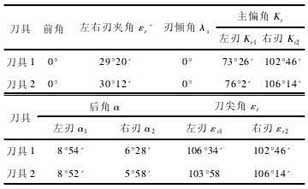
Two tools for turning the left and right thread faces of trapezoidal external thread with a pitch of 16 mm were designed and ground, The utility model adopts a replaceable cutter head spring type cutter, and the material is high speed steel (W18Cr4V), which can be installed and disassembled on the cutter body. The part where the two tools participate in the cutting is composed of the top edge and the left and right cutting edges. The specific structure is shown in Fig. 3.
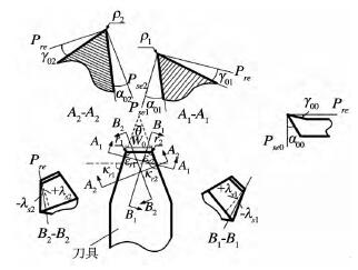
image 3. Tool cutting edge structure
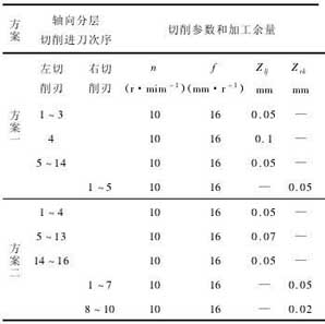
Using the above two tools on the CA6140 lathe, the rotational speed n is 10 r/min, keeping the cutting depth of the tool consistent with the depth of the workpiece thread groove. The screw specimens are machined by turning tool left and right and cutting edge layer by layer along one side of the axis respectively. Until the roughness of the machined surface of the left and right threads and the error of the thread diameter are controlled below the predetermined processing quality index. The two cutting schemes are shown in Table 4.
4, Thread axial layering cutting test results
The above experiment obtains the pitch error data curve of the left and right thread faces of the screw as shown in Fig. 4.
Meet the processing requirements.
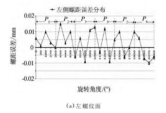
Figure 5 Scheme 2, experimental results of the thread surface pitch error
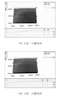
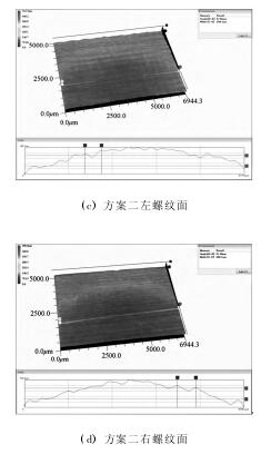
Image 6 Surface topography comparison of left and right thread surface
Two tools for turning the left and right thread faces of trapezoidal external thread with a pitch of 16 mm were designed and ground, The utility model adopts a replaceable cutter head spring type cutter, and the material is high speed steel (W18Cr4V), which can be installed and disassembled on the cutter body. The part where the two tools participate in the cutting is composed of the top edge and the left and right cutting edges. The specific structure is shown in Fig. 3.
image 3. Tool cutting edge structure
In the picture,
Pre: base surface,
Pse0: the cutting plane of the main cutting edge,
Pse1: the cutting plane for the left cutting edge,
Pse2: the cutting plane for the right cutting edge,
W0: the length of the top cutting edge,
θ: the angle between the left and right cutting edges,
λs: is the blade inclination angle,
γ00: is the top cutting edge rake angle,
γ01: is the rake angle of the left cutting edge,
γ02: is the right cutting edge rake angle,
α00: is the back angle of the top cutting edge,
α01: is the left corner of the cutting edge,
α02: is the right cutting edge back angle,
εr1: the cutting edge angle of the left cutting edge,
εr1: is the right cutting edge angle.
The tool geometry is shown in Table 3.
table 3 Tool geometry angle
Using the above two tools on the CA6140 lathe, the rotational speed n is 10 r/min, keeping the cutting depth of the tool consistent with the depth of the workpiece thread groove. The screw specimens are machined by turning tool left and right and cutting edge layer by layer along one side of the axis respectively. Until the roughness of the machined surface of the left and right threads and the error of the thread diameter are controlled below the predetermined processing quality index. The two cutting schemes are shown in Table 4.
Table 4 Finishing experiment plan
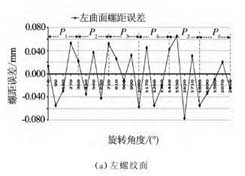
4, Thread axial layering cutting test results
The above experiment obtains the pitch error data curve of the left and right thread faces of the screw as shown in Fig. 4.
Figure 4 Scheme 1, experimental results of the thread surface pitch error
As shown in Figure 4, scenario one, The fluctuation range of the left surface pitch error is -0.019 ~ 0.019 mm, The fluctuation range of the pitch error of the right surface is -0.017 to 0.019 mm, The pitch error of the left edge cutting is larger than that of the right edge cutting, and the right side is denser than the left side. Among them, the right surface pitch error is better than the left surface, and both are between -0.02 and 0.02 mm.Meet the processing requirements.
Figure 5 Scheme 2, experimental results of the thread surface pitch error
As shown in Figure 5, Solution two, For the left curved surface, the pitch error ranges from -0.009 9 to 0.01 mm. For the right curved surface, the pitch error ranges from -0.01 to 0.01 mm. The pitch error of the left edge cutting is larger than that of the right edge cutting, and the left side is denser than the right side. Among them, the right surface pitch error is better than the left surface, and both are between - 0.02 ~ 0.02 mm, meeting the processing requirements. In order to quantitatively analyze the pros and cons of the machining accuracy of the left and right sides of the two solutions, the order of magnitude is 10-4mm. In order to quantitatively analyze the accuracy of the two sides of the thread, the order of magnitude is 10 - 4mm.
Correlation analysis of the pitch error of the left and right thread faces results in:
Solution 1: The pitch error of the left and right thread faces of the threaded test piece is 0.8632. Solution 2: specimen threaded surface of the right and left threaded screw pitch error associated degree of 0.6217. Therefore, it can be seen that the consistency of the thread surface distribution in the second scheme is better than that in the first scheme. The machined surface topography of the left and right thread faces of the screw obtained in the experiment is shown in Fig. 6.
Image 6 Surface topography comparison of left and right thread surface
In order to quantitatively analyze the pros and cons of the roughness parameters of the left and right sides of the whole thread, the roughness parameter curve is processed and analyzed. The results are shown in Table 5.
Table 5 Roughness Ra parameter value analysis
Table 5 Roughness Ra parameter value analysis
As can be seen from Table 5, The variation range, average value and standard deviation of the three roughness index values of the large pitch external thread in the second scheme are relatively small.
It shows that the thread surface roughness value of the large pitch external thread in the second scheme is small, and the distribution along the entire thread surface is relatively uniform and the consistency is good. It can also be seen from the comparison of the above two process schemes that the number of processing in the second scheme is much larger than that in the first scheme, but the processing effect is better than the scheme one. Therefore, it can be explained that the cutting efficiency in the design target conflicts with other targets. To ensure that other goals meet the requirements, just give reasonable design parameters. Consider and select reasonable cutting efficiency when other objectives meet the technical requirements and reach the highest value
From the above analysis, it can be seen that due to the difference of design variables, the processing surface topography of the same large pitch external threaded workpiece may vary greatly, which is caused by the difference of process design variables. This difference can lead to deviations in the transmission of motion and force. Under different process design conditions, the quality of the machined surface is quite different, and the consistency and distribution characteristics of the thread surface will be greatly different. Therefore, controlling the process design variables and optimizing the process scheme suitable for large-pitch thread cutting is essential for high-precision, high-quality large-pitch thread machining.
5 Conclusion
(1) Study on the contact relationship of large-pitch external thread cutters and the parameters of the cutting layer by axial stratification. 18 parameters such as tool geometry angle, cutting parameters and number of left and right edge cuttings were determined as process design variables; The key process design variable analysis results show that the front and rear cutting edges are designed to have a front angle of 0°. The to the influence of the right helix angle, the left edge is cut with positive front angle and the right edge is cut with negative front angle, and the screw angle has the opposite effect on the working rear angle of the left and right cutting edges . The left and right cutting edges use the same process design variable to cut the large pitch external thread, and the formation process of the left and right thread faces is obviously different;
(2) With the cutting efficiency and the consistency of the surface of the left and right thread surface, the design method of axially layered cutting process with large pitch external thread is proposed. This method adjusts the back angle of the left and right blades of the tool, the number of machining times of the left and right thread faces, and the machining allowance for a single cut. Under the condition of ensuring efficiency, the processing quality of the thread is effectively improved;
(3) Two different cutting process schemes were designed and proposed according to the design method. The comparison experiment of axial delamination cutting precision machining of large pitch external thread was carried out to determine the final process design. In this scheme, the left edge turning was carried out 16 times and the right edge turning was carried out 10 times. The tool front angle is 0°, the left blade back angle is 8°52', and the right edge back angle is 5°58'; The experimental results show that the design method can significantly improve the pitch error, surface roughness and its corresponding distribution of large pitch threads. To achieve the processing requirements of large pitch thread, this method can be used for the design of axially layered turning large pitch thread finishing.


