Application Case of Industrial Robot and CNC Machining
This article discusses the application process of the FANUC robot in the motor housing production line. Using robot automatic loading and unloading technology and the use of iRVision vision system, the robot trajectory can be planned rationally and the industrial robot handling technology and CNC machining technology can be organically combined. Automatic loading and unloading of workpieces, automatic stacking of finished products, and high-precision, high-efficiency and low-cost processing of products.
Keywords: industrial robots, CNC machining portfolio, industrial automation
1. FANUC robot
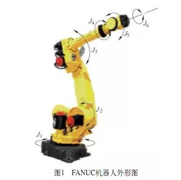
The automatic processing line is equipped with two FANUC Robot M-20iA handling system robots. One of the robots is a walking robot R1. Using FANUC servo motor αiF12/3000 control, transmission through precision reducer, gear and rack, high repeatability, can easily adapt to the machine layout on both sides of the rail.
It is mainly used for the grabbing of rough workpieces, loading of machine tools, and workpiece grabbing between machining processes, as well as the removal of processed products and their transport to conveyor belts. Another fixed robot R2 incorporates FANUC's unique intelligent robot technology (iRVision vision function) for blanking and stacking finished products in baskets. Each joint of each part of the FANUC Robot M-20iA robot is a joint point or coordinate system. The shape and position of each joint are shown in Figure 1.
Processing line equipment layout
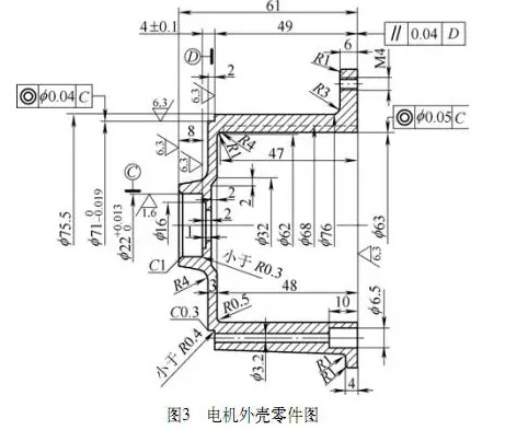
Figure 3. Motor housing parts drawing
The contents of the part processing operations are assigned as follows:
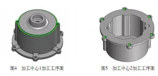
(1) VM850 vertical machining center 1, M4 threaded bottom hole drilling, M4 thread tapping and milling outside the cylindrical boss process, as shown in Figure 4.
(2) VM850 machining center 2, 6 φ5.5mm for drilling through-holes, apertures chamfering processing step, As shown in Figure 5.
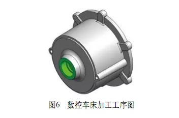
(3) The CLX360 numerical control lathe carries out the inner hole, the step hole and the hole chamfering process, as shown in Fig.6.
In addition, it is also necessary to design a special fixture. The fixture of the machining center adopts the internal clamping method, and the CNC lathe adopts the external clamping method. The combined application technology of robots and numerically-controlled machine tools is used to process the workpieces by automatic loading and unloading to improve processing efficiency.
4. Robot automatic loading and unloading action design
According to the shape characteristics of the workpiece design robot pneumatic grip parts, including pneumatic, sensors and mechanical parts.
Workpiece processing process is as follows:
1. Blank workpieces are placed on a feeding conveyor.
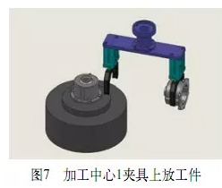
2. The walking robot R1 composite gripper grabs the rough workpiece, travels to the machining center 1 position, and installs the workpiece on the special fixture of the machining center 1. As shown in Figure 7.
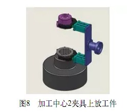
3.After the machining center 1 is finished, the walking robot R1 composite claw removes the workpiece, walks to the machining center 2 position, and installs the workpiece on the special fixture of the machining center 2. As shown in Figure 8.
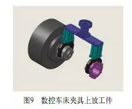
4. After the processing center 2 is finished, the walking robot R1 takes the workpiece to the position of the CNC lathe and mounts the workpiece on the special fixture. As shown in Figure 9.
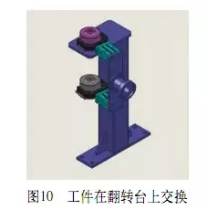
After the workpiece has been machined, the workpiece is removed and the robot walks to the position of the workpiece turning table to perform workpiece retroflexion and exchange. As shown in Figure 10.
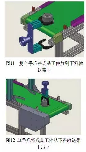
5. After the workpiece is exchanged at the turning table, the robot R1 places the finished product on the blanking conveyor. As shown in Figure 11.
The workpiece is unloaded by the robot R2 and automatically placed in the finished product basket. As shown in Figure 12.
(2) Vertical machining center 2 special fixture:
Vertical machining center 2, to drill 6 φ5.5mm through holes, hole chamfering process, designed to clamp the workpiece with a pneumatic three-jaw self-centering chuck, with two elastic V-block oriented fixture. As shown in Figure 14.
6. Robot, PLC and CNC Machine Interface
In order to ensure the safe cooperation between the robot and the CNC machine tool, a safe and reliable communication connection between the robot, the PLC and the CNC machine tool must be established.
In terms of hardware, the corresponding input and output points between the three are connected via shielded cables.
In terms of software, the current status of machine tools and robots is collected through special software for robots and PLC interfaces, and corresponding control programs that conform to the loading and unloading logic are programmed to achieve effective communication between CNC machine tools and robots.
Emphasis needs to deal with emergency stop signals, CNC machine ready signal, Robot gripper pneumatic signal, Loose clamp signals and safety gate signals of CNC machine tools, etc. CNC machine state monitoring screen shown in Figure 16.
7. Conclusion
With the development of industrial robots to a deeper and broader direction and the improvement of the level of intelligent robots, the scope of application of robots continues to expand. Industrial robot automatic loading and unloading mechanism as an auxiliary component of CNC machine tools, more and more attention by machine tool manufacturers and users.
The rapid and error-free communication between the robot control system and the machine control system, as well as the accuracy of the robot motion, ensures the reliability of the system's machining process. The automatic processing production line described in this article brings together advanced technologies such as robot technology, PLC technology, sensor detection technology, communication technology, and numerical control technology. The technical combination of industrial robots and CNC machine tools was realized, the operation mode of CNC machine tools was simplified, the operational safety of CNC machine tools was improved, and the labor intensity of workers was reduced. The workpiece loading and unloading and automatic processing are closely connected, which greatly improves the work efficiency and has a good application value.
Keywords: industrial robots, CNC machining portfolio, industrial automation
1. FANUC robot
The automatic processing line is equipped with two FANUC Robot M-20iA handling system robots. One of the robots is a walking robot R1. Using FANUC servo motor αiF12/3000 control, transmission through precision reducer, gear and rack, high repeatability, can easily adapt to the machine layout on both sides of the rail.
It is mainly used for the grabbing of rough workpieces, loading of machine tools, and workpiece grabbing between machining processes, as well as the removal of processed products and their transport to conveyor belts. Another fixed robot R2 incorporates FANUC's unique intelligent robot technology (iRVision vision function) for blanking and stacking finished products in baskets. Each joint of each part of the FANUC Robot M-20iA robot is a joint point or coordinate system. The shape and position of each joint are shown in Figure 1.
2. Automatic processing production line equipment layout
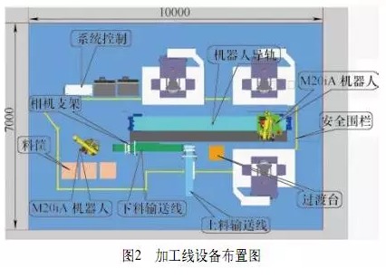
The motor housing automatic processing line consists of a feeding conveyor and a blanking conveyor belt (respectively equipped with iRVision vision system), Walking robot R1 (rail type), fixed robot R2, two VM850 vertical machining centers, one CLX360 CNC lathe, Finished basket, and system control cabinet, etc. The equipment layout is shown in Figure 2.
The motor housing automatic processing line consists of a feeding conveyor and a blanking conveyor belt (respectively equipped with iRVision vision system), Walking robot R1 (rail type), fixed robot R2, two VM850 vertical machining centers, one CLX360 CNC lathe, Finished basket, and system control cabinet, etc. The equipment layout is shown in Figure 2.
Processing line equipment layout
3. CNC machining process
The workpiece is the motor housing, as shown in Figure 3, for mass production, the material is ADC12 aluminum alloy. Machining content includes face milling drilling, tapping and bore turning.
The workpiece is the motor housing, as shown in Figure 3, for mass production, the material is ADC12 aluminum alloy. Machining content includes face milling drilling, tapping and bore turning.
Figure 3. Motor housing parts drawing
The contents of the part processing operations are assigned as follows:
(1) VM850 vertical machining center 1, M4 threaded bottom hole drilling, M4 thread tapping and milling outside the cylindrical boss process, as shown in Figure 4.
(2) VM850 machining center 2, 6 φ5.5mm for drilling through-holes, apertures chamfering processing step, As shown in Figure 5.
(3) The CLX360 numerical control lathe carries out the inner hole, the step hole and the hole chamfering process, as shown in Fig.6.
In addition, it is also necessary to design a special fixture. The fixture of the machining center adopts the internal clamping method, and the CNC lathe adopts the external clamping method. The combined application technology of robots and numerically-controlled machine tools is used to process the workpieces by automatic loading and unloading to improve processing efficiency.
4. Robot automatic loading and unloading action design
According to the shape characteristics of the workpiece design robot pneumatic grip parts, including pneumatic, sensors and mechanical parts.
Workpiece processing process is as follows:
1. Blank workpieces are placed on a feeding conveyor.
2. The walking robot R1 composite gripper grabs the rough workpiece, travels to the machining center 1 position, and installs the workpiece on the special fixture of the machining center 1. As shown in Figure 7.
3.After the machining center 1 is finished, the walking robot R1 composite claw removes the workpiece, walks to the machining center 2 position, and installs the workpiece on the special fixture of the machining center 2. As shown in Figure 8.
4. After the processing center 2 is finished, the walking robot R1 takes the workpiece to the position of the CNC lathe and mounts the workpiece on the special fixture. As shown in Figure 9.
After the workpiece has been machined, the workpiece is removed and the robot walks to the position of the workpiece turning table to perform workpiece retroflexion and exchange. As shown in Figure 10.
5. After the workpiece is exchanged at the turning table, the robot R1 places the finished product on the blanking conveyor. As shown in Figure 11.
The workpiece is unloaded by the robot R2 and automatically placed in the finished product basket. As shown in Figure 12.
This concludes a complete process. Each processing step has a corresponding beat. After adjusting the CNC machining program and robot motion program, it can realize the perfect combination of CNC machine tool processing and robot loading and unloading.
5. Special fixture design
According to the respective processing tasks of the three CNC machine tools, three sets of combined pneumatic clamps are designed and introduced as follows.
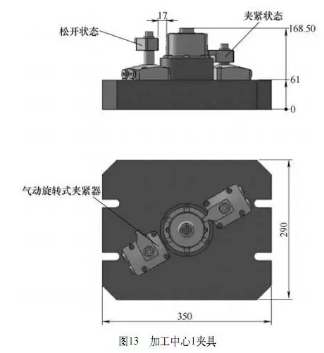
(1) Vertical machining center 1 special fixture:
Vertical Machining Center 1 for drilling, tapping and milling external bosses. Designing a fixture with two sides of a pin to position the workpiece and clamp it with a pneumatic rotating clamp. As shown in Figure 13.
5. Special fixture design
According to the respective processing tasks of the three CNC machine tools, three sets of combined pneumatic clamps are designed and introduced as follows.
(1) Vertical machining center 1 special fixture:
Vertical Machining Center 1 for drilling, tapping and milling external bosses. Designing a fixture with two sides of a pin to position the workpiece and clamp it with a pneumatic rotating clamp. As shown in Figure 13.
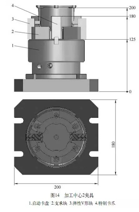
(2) Vertical machining center 2 special fixture:
Vertical machining center 2, to drill 6 φ5.5mm through holes, hole chamfering process, designed to clamp the workpiece with a pneumatic three-jaw self-centering chuck, with two elastic V-block oriented fixture. As shown in Figure 14.
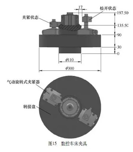
(3) CNC lathe special fixture:
The numerical control lathe carries out the processing of the inner hole, the step hole, and the hole chamfering process, and designs a fixture with a two-pin positioning work piece and a pneumatic rotating clamp clamping method. As shown in Figure 15.
The numerical control lathe carries out the processing of the inner hole, the step hole, and the hole chamfering process, and designs a fixture with a two-pin positioning work piece and a pneumatic rotating clamp clamping method. As shown in Figure 15.
6. Robot, PLC and CNC Machine Interface
In order to ensure the safe cooperation between the robot and the CNC machine tool, a safe and reliable communication connection between the robot, the PLC and the CNC machine tool must be established.
In terms of hardware, the corresponding input and output points between the three are connected via shielded cables.
In terms of software, the current status of machine tools and robots is collected through special software for robots and PLC interfaces, and corresponding control programs that conform to the loading and unloading logic are programmed to achieve effective communication between CNC machine tools and robots.
Emphasis needs to deal with emergency stop signals, CNC machine ready signal, Robot gripper pneumatic signal, Loose clamp signals and safety gate signals of CNC machine tools, etc. CNC machine state monitoring screen shown in Figure 16.
7. Conclusion
With the development of industrial robots to a deeper and broader direction and the improvement of the level of intelligent robots, the scope of application of robots continues to expand. Industrial robot automatic loading and unloading mechanism as an auxiliary component of CNC machine tools, more and more attention by machine tool manufacturers and users.
The rapid and error-free communication between the robot control system and the machine control system, as well as the accuracy of the robot motion, ensures the reliability of the system's machining process. The automatic processing production line described in this article brings together advanced technologies such as robot technology, PLC technology, sensor detection technology, communication technology, and numerical control technology. The technical combination of industrial robots and CNC machine tools was realized, the operation mode of CNC machine tools was simplified, the operational safety of CNC machine tools was improved, and the labor intensity of workers was reduced. The workpiece loading and unloading and automatic processing are closely connected, which greatly improves the work efficiency and has a good application value.


