5-axis machining of the integral impeller
The overall processing of the impeller is carried out by forming a hub and a blade on a blank, instead of using a process in which the blade is formed and welded to the hub. The processing scheme is as follows:
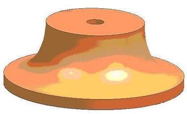
1. In order to improve the strength of the overall impeller, the blank is generally formed by forging, and then the turning of the reference surface is performed to process the basic shape of the impeller body. The blank of the air compressor rotor is shown in Figure 1.
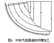
2. The position of the grooved machining groove of the impeller air flow passage should be selected in the middle position of the air flow passage. The flat-bottomed taper shank cutter is used to run parallel to the airflow passage, and to ensure a certain machining allowance for the bottom of the groove and the surface of the hub. as shown in picture 2.
 The flat-bottom taper shank milling cutter is a cemented carbide cutter whose specifications are:
The diameter of the flat bottom portion is: 3 mm, and the half cone angle is 2°;
The diameter of the tool handle is: 6mm;
The length of the tapered portion is: 20 mm.
The spindle speed selected in this step is: 10000r/min;
The feed rate is: 800 mm/min.
On the control panel of the CNC machine tool, the spindle speed and feed speed trimming (magnification) switch are generally provided, and the spindle speed and feed speed can be adjusted according to the actual machining conditions during the machining process.
3. The grooved machining of the impeller airflow passage and the roughing and slotting of the blade are processed by a spherical taper shank milling cutter, starting from the slotted position. From the center to the outer edge to the two sides of the blade expansion slot, the expansion of the groove to ensure that the blade has a certain finishing allowance. Normally, the grooved and finished milling hub surfaces are finished in one pass. Because the impeller is narrow, the blade is high, and the distortion is severe, and the UG numerical control machining programming needs to determine the cutting area according to the driving surface, the slotting processing needs to be processed in two parts. The first part: select the drive surface as the hub surface and expand the slot. At this time, it cannot be machined to the surface of the hub, and further slotting processing is required; The second part: further slot expansion and roughing of the blade. The driving surface is selected as the offset surface of the blade surface, and the groove is further expanded while the blade is roughed.
The spherical taper shank milling cutter is a cemented carbide cutter.
Its specifications are:
The diameter of the ball head portion is: 3 mm, and the half cone angle is 2°;
The diameter of the tool handle is: 6mm;
The length of the tapered portion is: 20mm;
The spindle speed selected in this step is: 20000r/min;
The feed rate is 3000 mm/min.
4, the finishing of the blade and the wheel hub under the uniform margin, to ensure a good surface processing quality, using ball-end milling cutter finishing. Because the minimum spacing between adjacent blades is 3.1mm, and the deepest point of the blade is 17.15mm. Taking into account the interference, the rotor finishing tool uses a 2.5-diameter ball-end bar milling cutter from Fraisa, Switzerland, with a cutter avoidance of 20 mm.
The spindle speed during machining is: 260000r/min,
The feed rate is: 5000 mm/min.
5, The finishing is rounded with large and small blades, and the left side is rounded. The fillet radius varies linearly from 1.25 mm to 2.2 mm to 1.25 mm from the leading edge to the trailing edge of the blade. The maximum fillet occurs 22% near the trailing edge. The right side of the blade is a constant fillet of 1.25 mm. Rounding can be done in one pass, when the radius of the ball head portion is large enough to be the smallest radius of the rounded corner. The selected tool, spindle speed, feed rate, and finishing of the blade and hub. The above procedures must be indexed and rotated to process the complete hub or blade and then execute the next procedure to ensure uniform stress release and reduce machining deformation errors.
1. In order to improve the strength of the overall impeller, the blank is generally formed by forging, and then the turning of the reference surface is performed to process the basic shape of the impeller body. The blank of the air compressor rotor is shown in Figure 1.
2. The position of the grooved machining groove of the impeller air flow passage should be selected in the middle position of the air flow passage. The flat-bottomed taper shank cutter is used to run parallel to the airflow passage, and to ensure a certain machining allowance for the bottom of the groove and the surface of the hub. as shown in picture 2.
The diameter of the flat bottom portion is: 3 mm, and the half cone angle is 2°;
The diameter of the tool handle is: 6mm;
The length of the tapered portion is: 20 mm.
The spindle speed selected in this step is: 10000r/min;
The feed rate is: 800 mm/min.
On the control panel of the CNC machine tool, the spindle speed and feed speed trimming (magnification) switch are generally provided, and the spindle speed and feed speed can be adjusted according to the actual machining conditions during the machining process.
3. The grooved machining of the impeller airflow passage and the roughing and slotting of the blade are processed by a spherical taper shank milling cutter, starting from the slotted position. From the center to the outer edge to the two sides of the blade expansion slot, the expansion of the groove to ensure that the blade has a certain finishing allowance. Normally, the grooved and finished milling hub surfaces are finished in one pass. Because the impeller is narrow, the blade is high, and the distortion is severe, and the UG numerical control machining programming needs to determine the cutting area according to the driving surface, the slotting processing needs to be processed in two parts. The first part: select the drive surface as the hub surface and expand the slot. At this time, it cannot be machined to the surface of the hub, and further slotting processing is required; The second part: further slot expansion and roughing of the blade. The driving surface is selected as the offset surface of the blade surface, and the groove is further expanded while the blade is roughed.
The spherical taper shank milling cutter is a cemented carbide cutter.
Its specifications are:
The diameter of the ball head portion is: 3 mm, and the half cone angle is 2°;
The diameter of the tool handle is: 6mm;
The length of the tapered portion is: 20mm;
The spindle speed selected in this step is: 20000r/min;
The feed rate is 3000 mm/min.
4, the finishing of the blade and the wheel hub under the uniform margin, to ensure a good surface processing quality, using ball-end milling cutter finishing. Because the minimum spacing between adjacent blades is 3.1mm, and the deepest point of the blade is 17.15mm. Taking into account the interference, the rotor finishing tool uses a 2.5-diameter ball-end bar milling cutter from Fraisa, Switzerland, with a cutter avoidance of 20 mm.
The spindle speed during machining is: 260000r/min,
The feed rate is: 5000 mm/min.
5, The finishing is rounded with large and small blades, and the left side is rounded. The fillet radius varies linearly from 1.25 mm to 2.2 mm to 1.25 mm from the leading edge to the trailing edge of the blade. The maximum fillet occurs 22% near the trailing edge. The right side of the blade is a constant fillet of 1.25 mm. Rounding can be done in one pass, when the radius of the ball head portion is large enough to be the smallest radius of the rounded corner. The selected tool, spindle speed, feed rate, and finishing of the blade and hub. The above procedures must be indexed and rotated to process the complete hub or blade and then execute the next procedure to ensure uniform stress release and reduce machining deformation errors.


