Welding of Aluminum And Aluminum Alloys
■ Analysis material analysis 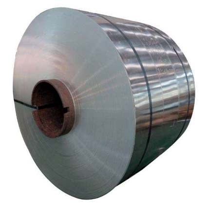
Industrial pure aluminum has the general characteristics of aluminum, low density, good electrical and thermal conductivity, good anti-corrosion performance, good plastic processing performance, can be processed into plates, strips, foils and extrusion products, etc., can be gas welding, argon arc welding, spot welding. Industrial pure aluminum can not be heat-strengthened, can increase strength through cold deformation, the only heat treatment form is annealing, the onset temperature of recrystallization is related to the content of impurities and the degree of deformation, and is generally around 200°C. The annealed sheet has σb=80 to 100 MPa, σ0.2=30 to 50 MPa, ζ=35% to 40%, and HB=25 to 30. After 60% to 80% cold deformation, although it can be increased to 150 to 180 MPa, the enthalpy decreases to 1% to 1.5%. Increasing the content of iron and silicon impurities can increase the strength but reduce the plasticity, electrical conductivity, and corrosion resistance.
The following is the chemical composition of the parent material
■ Analysis of Weldability of Aluminum
I. Analysis of physical and chemical properties
The melting point of pure aluminum is low (660°C). When melting, the color does not change, it is difficult to observe the molten pool, and it is easy to collapse and burn through during welding. Thermal conductivity is three times that of low-carbon steel, heat dissipation is fast, and it is not easy to melt when welding; The coefficient of linear expansion is twice that of low carbon steel and it is easily deformed during welding. It is easily oxidized into dense, high-melting oxide film Al2O3 (melting point 2050°C) in the air. It is infusi- ble and non-conductive. It may cause unfused, slag inclusion, and unstable welding during welding. Therefore, the weldability of pure aluminum is worse than that of low carbon steel. Therefore, the welding properties of pure aluminum mainly include: easy oxidation during the welding process, high energy consumption, easy generation of pores (mainly hydrogen gas pores), easy formation of hot cracks in welding, easy softening of welded joints, welded joints have reduced corrosion resistance.
1, easy oxidation
Aluminum 1060 and oxygen affinity is very large, at room temperature, aluminum easily oxidized together, the formation of a dense Al2O3 film on the surface of aluminum, can prevent the continued oxidation of metal, is beneficial to the natural anti-corrosion, but it has brought difficulties to the welding . This is due to the high melting point of the alumina film (about 2050°C), far exceeding the melting point of the aluminum 1060, and the high density of 3.95-4.10 g/m2, which is about 1.4 times that of the aluminum 1060, plus a very high thermal conductivity of 1060. Welding It is easy to cause non-fusion phenomena, and it is also likely to become inclusions of weld metal and form slag inclusion defects. At the same time oxide film can absorb more moisture, welding will cause the weld to generate pores.
 2, easy to produce air hole
Since aluminum 1060 does not contain carbon, there is no condition for the formation of CO air holes, and nitrogen is insoluble in aluminum, so it is generally believed that the main reason for aluminum 1060 generating air holes is hydrogen. Hydrogen is largely soluble in liquid aluminum and almost insoluble in solid aluminum. At high temperatures of welding, the solubility of hydrogen in liquid aluminum decreases sharply. If the bath metal dissolves in supersaturated hydrogen, supersaturated hydrogen will precipitate out of the liquid metal to form tiny bubbles at a certain cooling rate. The precipitation of hydrogen in the solidification process of aluminum melt pools on the one hand forms new, tiny, small bubbles, and on the other hand it expands into already formed tiny bubbles and grows. At the same time, due to the small relative density of aluminum 1060, the bubble floats slowly. If the cooling rate is faster, the bubbles will not escape the molten pool, leaving the air hole in the weld after solidification. If the solidification process of the molten pool is relatively slow, there will be enough time for the hydrogen bubbles to escape the molten pool and no air hole will be formed in the weld. On the other hand, if the solidification rate of the molten pool is very fast, hydrogen can not be precipitated from the liquid metal, but the supersaturated solid solution is formed in the molten aluminum, and the gas will not be precipitated to form air hole. It can be seen that the cooling rate is one of the important conditions that affect the generation of air holes.
3, welding hot crack
Aluminium 1060 non-heat-strengthening alloys rarely produce cracks during melt welding. Cracks can only occur if the impurity content exceeds the specified range or if the rigidity is high. The cause of thermal cracking in aluminum 1060 is related to its composition and welding stress. Since aluminum 1060 has a coefficient of linear expansion that is nearly twice that of iron, and its solidification shrinkage is twice as large as that of iron, the welding stress of the aluminum weldment is large.
4, high thermal conductivity and conductivity
The thermal conductivity of aluminum 1060 is very large, about four times that of steel, and its heat capacity is nearly double that of steel. Therefore, welding aluminum 1060 consumes more heat than steel. In order to obtain high-quality welded joints, it is necessary to use a heat source with concentrated energy and large power to perform normal welding, especially when the workpiece thickness is large. Aluminium 1060 has good electrical conductivity, and resistance welding requires more power.
5, high temperature makes the strength and plasticity low
The strength and plasticity of aluminum 1060 at high temperatures is very low, such as 370 °C strength is only about 1MPa, often can not support the weight of liquid pool, Destruction of the formation of weld metal, sometimes also cause the collapse of the weld metal and burn through.
6, no color change
When aluminum 1060 changes from solid to liquid, there is no obvious color change, so it is not easy to judge the temperature of the bath. In addition, when the temperature rises, the strength of aluminum 1060 decreases. Therefore, it is difficult to grasp the heating temperature during welding, and it is often not possible to perceive the burn-through due to an excessively high temperature.
In general, aluminum 1060 has good weldability. As long as the above welding characteristics are properly selected, the welding method, welding material, pre-weld cleaning and welding operation process can be properly used to obtain a good welded joint.
The thickness of the shell shell is 16mm, so before welding, in order to avoid hot cracks, it should be preheated with a preheating temperature of 120-140°C.
(2) Improper welding methods
For example, if the energy of the submerged arc welding line is large, coarse grain structure will appear in the heat-affected zone of the welding heat-affected zone, and the toughness of the heat-affected zone will be reduced. The energy of electroslag welding is even greater than that of submerged arc welding. The grains in the heat affected zone are more coarse and the toughness is reduced more obviously. Therefore, after the automatic argon-arc welding of pure aluminum, the grains are usually refined by normalizing to improve the toughness.
Welding process plan
The welding equipment is a NB-500 MIG gas shielded welding machine with a current regulation range of 50 to 500A. The diameter of the welding wire is Φ1.6mm and the protective gas, argon, has a purity of not less than 99.96%. The reason for its choice is as follows:
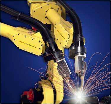
(1) In addition to CO2 gas shielded welding, almost all welding methods can be used for welding aluminum and aluminum alloys, but aluminum and aluminum alloys have different suitability for various welding methods, and various welding methods have their own applications.
Gas welding and electrode arc welding methods are simple and easy to operate. Gas welding can be used to repair welding of thin aluminum plates and castings that do not require high welding quality. Welding electrode arc welding can be used for welding aluminum alloy castings. Inert gas shielded welding is TIG welding and MIG welding, they are the most widely used aluminum and aluminum alloy welding methods. From the "cathode cleaning" role and the tungsten maximum current, tungsten-arc welding is generally used. Because it is under the good protection of argon welding, the molten pool can be protected from oxygen, hydrogen and other harmful gases. The argon arc welding current is stable, the heat is concentrated, the weld tissue is compact, the appearance is beautiful, the strength and the plasticity are high, and the deformation of the workpiece is small.
However, due to the limited current of tungsten, the arc's penetration force is small and productivity is low. Therefore, it is generally used for welding thin plates with a thickness of 6 mm or less.
MIG arc power, heat concentration, heat affected zone is small, productivity can be more than three times more than TIG welding. Therefore, it is suitable for the welding of thick plate structures. It can weld aluminum and aluminum alloy plates below 50 mm. Welding of 30 mm thick aluminum plates can be done without preheating. Semi-automatic MIG welding is mainly used for tack welding, intermittent small welds and welding of irregularly shaped workpieces.
 (2) The thermal conductivity and specific heat capacity of aluminum and its alloys are more than two times lower than those of carbon steel and low alloy steel. The thermal conductivity of aluminum is more than ten times that of austenitic stainless steel. In the welding process, a large amount of thermal energy is rapidly transferred to the inside of the matrix metal. Therefore, when welding aluminum and aluminum alloys, the energy is consumed in the molten metal pool, and more heat is consumed in other parts of the metal.
This kind of useless energy consumption is more significant than steel welding. In order to obtain high-quality welded joints, it should be possible to use energy-concentrated, high-power energy, and preheating and other technological measures.
MIG welding compared with TIG welding, MIG welding of the minimum heating area of 10-4cm2, the maximum power density of 104 ~ 105w • cm-2, The minimum heating area of TIG welding is 10-3cm2, and the maximum power density is 1.5-104w•cm-2. Therefore, it is better to use MIG welding.
(3) Selection of aluminum and aluminum alloy welding wire In addition to considering good welding process performance, the tensile strength and plasticity (through bending test) of the butt joint should meet the specified requirements according to the requirements of the container. For vessels with corrosion resistance requirements, the corrosion resistance of the welded joints should also be at or close to that of the parent metal. Therefore, the selection of welding wire is mainly based on the following principles:
1. The purity of pure aluminum welding wire is generally not lower than that of the parent metal;
2. The chemical composition of the aluminum alloy welding wire is generally corresponding to or similar to the parent metal;
3. The content of corrosion resistant elements (magnesium, manganese, silicon, etc.) in aluminum alloy welding wire is generally not lower than that of parent metal;
4. When the dissimilar aluminum is welded, the welding wire should be selected according to the parent material with high corrosion resistance and high strength;
5. High-strength aluminum alloys that do not require corrosion resistance (heat-treated reinforced aluminum alloys) may use dissimilar alloy wires, such as SAlSi-1, which has good crack resistance, and may have lower strength than the base metal.
According to the use of aluminum storage tanks, in accordance with the above principles (equal strength, etc.), the wire is now selected as SAl-2, whose aluminum content is higher than 1060 (L2) industrial pure aluminum, in order to ensure the corrosion resistance of welded joints. .
(4) Protection gas selection
Aluminum and aluminum alloy MIG welding, using only inert gas argon or helium, no reactive gas is used. Although argon or helium is a protective gas, its physical properties are different, and thus its process performance is also different. The density of argon is about 1.4 times that of air, heavier than air; The density of helium is approximately 0.14 times that of air, lighter than air. When welding in the flat welding position, the argon gas sinks and drives away the air. This protects the arc and covers the weld zone. If helium gas protection is selected, the same protective effect is obtained. The flow and consumption of helium gas is approximately 2 to 3 times higher than that of argon gas.
In addition, the thermal conductivity of helium is higher than that of argon, and an arc plasma with a more uniform energy distribution can be generated. The argon arc plasma has a high center energy of the arc column, and its peripheral energy is low. Therefore, the shape of the weld during the Xenon arc MIG welding is characterized by deep penetration and wide melting, and the bottom of the weld is circular arc. However, the center of the weld of argon MIG welding has a narrow and deep "finger-like" penetration, with shallower penetration on both sides.
The ionization potential of helium is higher than that of argon. When the arc length and the welding current are constant, the arc voltage of the helium gas protection is higher than that of the argon arc. Thus, pure helium protective MIG welding, it is difficult to achieve an axial jet transition, Frequent splashes and rougher weld surfaces often occur. Argon-protected MIG welding is easier to achieve jet transition.
Due to the low arc voltage and low arc energy density of MIG argon arc welding, the arc is stable and has very few splashes, making it suitable for welding thin parts. MIG xenon arc welding has a high energy density and is suitable for welding thick parts, but the arc is not stable enough and helium is expensive.
The maximum wall thickness of this product is 16mm, so use argon as the protective gas.
3. Preparation before welding
(1) Groove form, joint form and size
Groove form, joint form and size depend on the thickness of aluminum weldment, welding position, droplet transfer form and welding process.
When the weldment thickness, welding position and welding process are fixed, the droplet transfer form is an important condition for determining the form of the groove and welding process parameters.
The form of droplet transfer in MIG welding and the stability of its process are the key to the suitability of the MIG welding method. When the welding current increases from small to large, the droplet transition from the short-circuit transition, drop-like transition, to the injection transition (shooting droplet transition, jet transition) direction. Short-circuit transition is only applicable to MIG welding of thin-walled parts with a material thickness of 1 to 2 mm. The injection transition process is relatively stable and can be used for MIG welding of various thickness aluminum materials. Between the short-circuit transition and the jet transition, there is a sub-jet transition zone where no short circuit occurs despite the short arc length. Even if the arc length changes, the current and voltage can remain unchanged. Even with a constant current source (deep drop external characteristics), the arc can be self-regulating, the welding process is stable, and the weld is shaped evenly and beautifully. Practical experience shows that when sub-jet transition MIG welding of aluminum is used, welding efficiency is higher and welding quality is better. MIG welding, the general use of DC reverse connection, do not use DC positive or AC, automatic welding and semi-automatic welding two ways.
Employed in the form of jet transition, the transition time of injection, narrow and deep weld easily presented finger penetration, weld both sides of poor penetration, porosity cracks and other defects. When sub-jet transitions are used, the arc length is shorter, the arc voltage is lower, the arc is slightly detonated, and the droplets at the end of the wire grow to equal the diameter of the wire as it transitions to the molten pool along the axis. There may be an instantaneous short circuit during this period. In the sub-jet transition MIG welding, the cathode atomization area is large, the bath protection effect is good, the weld seam is formed well, and the weld seam defects are small. For this reason, aluminum storage tanks should fully consider the above issues in the selection of welding parameters and groove design.
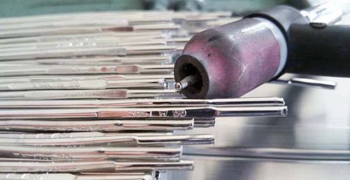
(2) Cleaning before welding
The oxide film and contaminants on the surface of the aluminum weldment and the wire can cause the static curve of the arc to move downward during the MIG welding process. As a result, the current of the weldment increases suddenly, the melting speed of the wire increases, and the arc lengthens.
At this point, the sound of the arc also changed from the rhythmic buzzing sound to the harsh call sound. Therefore, MIG welding parts and wire surface should be strictly cleaned, the quality of its cleaning will directly affect the quality of welding processes and joints, such as the tendency of weld porosity and mechanical properties. Welds and wire MIG welding surface cleaning, often using chemical cleaning and mechanical cleaning methods. At the same time, aluminum and aluminum alloy welding wire is best to use a smooth, smooth, bright "trilight" welding wire with special surface treatment.
1. Chemical cleaning
High chemical cleaning efficiency, stable quality, suitable for clean welding wire and small size, batch production of workpieces. Available dip method and scrub method two. Can be used acetone, gasoline, kerosene and other organic solvents to the surface of the oil, with 40 °C ~ 70 °C 5% ~ 10% NaOH solution alkaline wash 3min ~ 7min (a little longer but not more than 20min pure aluminum), rinse with water, Then it is pickled with 30% HNO3 solution at room temperature to 60°C for 1 minute to 3 minutes, rinsed with flowing water, air-dried or dried at low temperature.
2. mechanical cleaning
Mechanical cleaning is often used when the workpiece has a large size, a long production cycle, multi-layer welding, or chemical cleaning. First use acetone, gasoline and other organic solvents to wipe the surface to remove oil, then directly use a copper wire brush with a diameter of 0.15mm to 0.20mm or a stainless steel wire brush to brush until the metal luster is exposed. Generally, it is not suitable to grind with grinding wheel or ordinary sandpaper, so as to avoid the sand particles remaining on the metal surface, and the defects such as slag inclusion will be generated when welding. In addition, the surface to be welded may be cleaned with a spatula, a file, or the like.
After the workpiece and welding wire are cleaned and cleaned, an oxide film will be regenerated during storage. Especially in a humid environment, the oxide film grows faster in an environment polluted by acids, alkalis, and other vapors. Therefore, after cleaning and cleaning of workpieces and welding wire, the storage time before welding should be shortened as much as possible. In wet climates, welding should generally be performed within 4 hours of cleaning. After cleaning, if the storage time is too long (such as more than 24h) should be re-treated.
The cleaning plan adopted by this tanks is:
Oxides and other debris within 50 mm of the groove and its periphery should be cleaned. First use a stainless steel wire wheel with a diameter of less than 0.2mm for cleaning and then chemical cleaning. Welding wire is only chemically cleaned. The cleaned groove should be welded within 2 hours, and the exposed wire in the atmosphere after washing and drying should not exceed 4 hours.
The chemical cleaning parameters of aluminum tanks are shown in Table 1:
4. Preparation of process equipment
The process equipment required for MIG welding includes welding trolleys and rails, manipulators, positioners, roller carriers, and clamps for weldments. The main welding seams for aluminum storage tanks are single-sided and single-pass welding with V-shaped groove. In order to ensure penetration and prevent metal leakage in the molten pool, a method of adding a reverse surface gasket is adopted. Here only the main tooling selection.
(1) Liners
MIG welding, like TIG welding, sometimes requires a backside weld, because MIG welding power is greater, penetration ability is stronger, The back pad is not only beneficial to prevent metal leakage in the bath, but also helps to reduce the size of the joint. The operating conditions are more relaxed, and the requirements for operating skills can be appropriately reduced. The longitudinal and girth welds of the aluminum storage tank are all made of temporary pads, and the material is the same as that of the base metal, which can not only pollute the molten pool but also facilitate heat dissipation. The back gasket is installed in the tire fixture of the weldment, corresponds to the weld seam position, and is tightly attached to the opposite sides of the two parts. After welding, it is separated from the weldment.
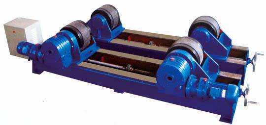
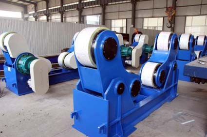
(2) roller carriage
The roller carriage is a commonly used process equipment for the manufacture of pressure vessels. The welding roller frame drives the roller through the motor and utilizes the friction between the driving roller and the welding piece to drive the displacement machine that rotates the tubular welding piece at a certain speed. The welding roller frame used in welding production is usually composed of a pair of active roller frames and a pair of passive roller frames.
The welding roller frame is mainly used for the assembly and welding of cylindrical barrels. When the tubular girth welding is performed, since the cylinder rotates on the roller, the all-position welding of the annular weld is changed to flat welding, which is favorable for improving the quality of the weld and the welding productivity. When the installation heights of the active roller bracket and the passive roller bracket are different, the assembly and welding of the cone and the unequal-diameter cylinder weldment can also be performed. For rectangular section weldments and irregularly shaped weldments, they can be mounted in special ring clamps or on roller carriages.
Welding roller frame can be divided into:
Universal type welding roller frame and special purpose welding roller frame are now use universal type..The most commonly used universal welding roller carriages in industrial production can be divided into two categories: One is a self-adjusting welding roller frame, and the other is an adjustable welding roller frame.
The characteristic of self-adjusting welding roller frame is that each roller frame consists of two sets of double rollers. Each group of roller brackets can rotate centered on its fulcrum so that it can adapt to different diameters of weldments over a relatively wide range without changing the distance between the two sets of rollers. However, when welding small-diameter weldments, the outer circle of the weldment can only be in contact with the two rollers of each pair of roller frames, and the load capacity of the roller frame will be reduced to 75% of the rated load accordingly.
Self-adjusting welding roller frame usually adopts dual drive transmission mode. The motor transmits the torque to the two sets of rollers through the secondary reducer and the connecting shaft to achieve a smooth rotation speed. The drive motor can use electromagnetic stepless speed regulation or inverter stepless speed regulation.
The characteristic of the adjustable welding roller frame is that the distance between the rollers of each roller frame is adjustable to adapt to different diameter welding pieces. Roller spacing can be adjusted by various methods. The simplest method is to drill two rows of bolt holes with the same hole spacing on the surface of the roller frame bearing. The roller seat is installed in the corresponding hole position according to the diameter of the weldment. Bolt fixed. When the diameter of the workpiece to be welded is constantly changing, the screw pitch can be used to adjust the wheel pitch. For the application field with a small range of weldment diameters, the linkage mechanism can be used to adjust the wheel spacing, which is very simple and saves auxiliary time.
Adjustable welding roller frame usually uses a pair of active roller frame and a pair of passive roller frame to perform assembly and welding operations. The active roller carriage can be divided into single drive and dual drive. Both motors can be started synchronously via electronic circuits. The advantage of dual drive is that the weldment rotates smoothly and eliminates bouncing. China has developed the industry standard JB/T9187-1999 for welding roller carriages. From the point of view of safety, and considering the reasonable choice of wheel drive power, the JB/T9187 industry standard also specifies that the wrap angle α of the center of the wheel to the center of the weldment should be controlled within the range of 45° to 110°. In the actual welding production, the selection procedure of the welding roller frame is as follows:
1. According to the specification and weight of the weldment specified in the factory's production program, and the monthly production capacity, the specifications of the welding roller frame, the rated load capacity and the quantity to be equipped are tentatively determined.
2. The structure of the roller is determined according to the weight of the weldment and the type of material. For stainless steel, titanium alloy and aluminum alloy pressure vessels, rubber or polyurethane wheels must be used.
3. According to the welding process method to be adopted, determine the requirements for the speed range of the welding roller frame and other technical characteristics.
4. According to the quality requirements of the weld, the control precision of the roller line speed of the welding roller frame should be proposed.
5. should consider the working environment.
Considering versatility, the aluminum storage tank adopts EB-10TN type adjustable welding roller frame, its technical parameters are:
Maximum load 5t, maximum rotation capacity 10t, roller line speed 70-1200mm/min,
Workpiece diameter 150-4000mm, number of rubber wheels 6, center distance between wheels 410 to 1810,
Dimensions: driving wheel 3300×890, driven wheel 2600×500×515, roller diameter (rubber wheel 350),
Weight: driving wheel 600, passive wheel 400.
(3) Welding manipulator
Welding machine, also called welding machine positioner, accurately delivers the welding head and keeps it in the position to be welded. Or at the selected welding speed, the welding head is moved along the specified trajectory, and the welding head displacing machine that completes the welding operation is matched. Used in conjunction with the welding positioner, it can be used to complete a variety of welds, such as automatic welding of longitudinal joints, ring joints, butt joints, fillet welds, and arbitrary curve welds. It is also possible to carry out automatic surfacing and cutting processes on the workpiece surface.
There are many kinds of welding manipulators, and the following types are common: Platform-type manipulators, cantilever manipulators, telescopic arm manipulators, door and bridge manipulators, etc.
The platform manipulator is mainly used for the welding of outer longitudinal seams and outer ring seams of cylindrical containers. The cantilever manipulator is mainly used to weld the inner longitudinal seam and the inner annular seam of the container. The telescopic arm type has many advantages. In addition to the use of the first two, you can also complete operations such as cutting, grinding, and flaw detection. It is proposed to use a telescopic arm manipulator.
5. Assembling and welding
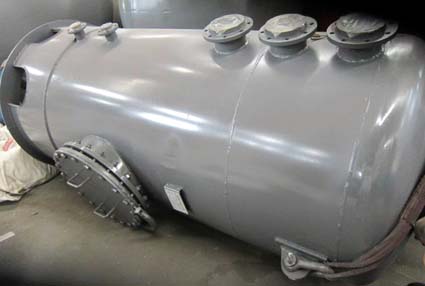
The aluminum storage tank is composed of a cylinder body, a sealing head and a connecting tube. The aluminum storage tank is separately assembled and welded, and then the cylinder body, the sealing head and the connecting tube are welded together.
But the main force element is the head and the cylinder. Next, we will explain the manufacturing process of aluminum storage tank by the specific production process of head and cylinder.
(1) Head manufacturing
The aluminum tank uses an oval head structure, According to the size, pure aluminum 1060 (L2) sheet with the size of -16×2000×5800mm can be used for press forming. The specific process is as follows:
Material selection→Retesting→Leveling→Drawing→Under material→ Forming→Secondary Scribing→Head Balance Cutting→Ring Groove Processing→ Dashing (holes) → Hole machining → re-examination dimensions → cleaning before welding → assembly.
The quality of pure aluminum 1060 (L2) sheet should meet the quality required by national standards.
The elliptical head is round before it is pressed. According to the formula Dp=k(Dn+δ)+2h, the developed size is Φ1258mm. After considering the shrinkage and machining allowance, the blanking size is Φ1270mm. Head size prior to compression molding press polished straight edge, followed by the press, with a punch and die press forming.
The formed head is also edge-processed to facilitate barrel assembly. That is to say, on the platform, a processing position line that guarantees the straight edge height is drawn, and it is selected to complete the remaining amount cutting and bevel processing at the same time in the ordinary vertical vehicle so as to meet the requirements of design drawings. After the head is finished, the inner surface of the head should be inspected. The method is to check the inner template with a chord length equal to 3/4Di of the inner diameter of the head.
The maximum clearance shall not be greater than 1.25% of the internal flow of the head. When checking, the template shall be perpendicular to the surface to be measured.
For the head with liquid outlet, two processes of Ø100mm hole scribe and hole processing are required after the head rest cutting process and the inspection process.
(2) Manufacturing of tube sections
The aluminum storage tank is composed of 3 barrel sections. The 3 barrel sections are made of two pieces of 6×1888×786mm pure aluminum plate 1060 (L2). Each section has a hole but different hole diameters. When assembling, it is necessary to ensure that the three holes are directly above the cylinder, and that the longitudinal joints of the three cylinder sections on the cylinder are staggered by a sufficient distance. Therefore, attention should be paid to the hole's positioning size when cutting material. For details, see the tube section process card.
The tube section manufacturing process is as follows:
Material selection→Retest→Leveling→Scribe→Check→ Cutting → Groove processing → Cleaning before welding → Patchwork assembly → Patchwork welding → Roll forming → Cleaning before welding → Longitudinal seam assembly → Longitudinal seam welding → Weld inspection → Straightening → Review dimensions → Assembly.
Choose 6×1000×2000mm pure aluminum 1060 (L2) plates, and the quality should meet the quality required by national standards. The tube section is generally rolled on a coiling machine. Since the inner diameter of the tube section is much larger than the wall thickness, Therefore, the development length L of the tube blank is calculated as the average diameter Dp of the tube section.
That is, L = πDp = π (Dg + δ) = 3787mm Dg - the inner diameter of the tube section δ - the wall thickness of the tube section
After the tube section is unfolded, it is rectangular, and its blanking size should also consider the shrinkage and machining allowance, and note that the unfolding direction of the tube section is consistent with the direction of the rolling fiber of the board. The line includes the cutting position line, the edge line, the hole center line and the position line, and the mark is marked. Should also check the rectangular diagonal, error ≤ 2mm.
The clean-up work should be done before welding, and when the assembly welding is performed, the welding is positioned on the front of the groove. The weld should be thin, and the length of the tack weld is generally 40-60mm.
Tube sections can be cold-rolled on three- or four-roller coiling machines. In the process of rolling, you should often check the curvature with a template. The amount of longitudinal misalignment and longitudinal misalignment at the longitudinal seam of the reeled circle shall meet the technical requirements. (Assembly tack welding gap 0 ~ 2mm; wrong side <1mm; ellipticity ≤ 1mm)
After the tube section has been rolled, the longitudinal joints should be assembled before the longitudinal seam welding. Leverage - screw tensioners, spiral pressure horses and other fixtures to eliminate the quality problems after rolling, Meet the assembly technology requirements for butt joints of longitudinal joints to ensure welding quality. Tack welding is performed after assembly. The longitudinal groove of the tube section is processed before being rolled, and the cleaning on both sides of the groove should be observed before welding.
The welding quality of the longitudinal joints of the tube section is required to be high. During the welding, the welding test plate of the aluminum storage tank was made.
At the same time, due to the poor quality of arc welding and arc extinguishing, Therefore, arc welding plates and lead plates having a length of 100 mm, a width of 80 mm, and a workpiece were mounted on both ends of the longitudinal weld before welding. See FIG. 2 for the assembling conditions. After the longitudinal joints of the tubular section are welded, non-destructive inspections shall be carried out as required, and then they shall be straightened to meet the roundness requirements before being sent to the assembly.
Industrial pure aluminum has the general characteristics of aluminum, low density, good electrical and thermal conductivity, good anti-corrosion performance, good plastic processing performance, can be processed into plates, strips, foils and extrusion products, etc., can be gas welding, argon arc welding, spot welding. Industrial pure aluminum can not be heat-strengthened, can increase strength through cold deformation, the only heat treatment form is annealing, the onset temperature of recrystallization is related to the content of impurities and the degree of deformation, and is generally around 200°C. The annealed sheet has σb=80 to 100 MPa, σ0.2=30 to 50 MPa, ζ=35% to 40%, and HB=25 to 30. After 60% to 80% cold deformation, although it can be increased to 150 to 180 MPa, the enthalpy decreases to 1% to 1.5%. Increasing the content of iron and silicon impurities can increase the strength but reduce the plasticity, electrical conductivity, and corrosion resistance.
The following is the chemical composition of the parent material
Table 2-1 Chemical composition of the base material (L2) (GB / T3190-1996)
| Grade | Al | Si | Mn | Fe | Cu |
| L2 | 99.6 | 0.25 | 0.03 |
0.35 |
0.05 |
■ Analysis of Weldability of Aluminum
I. Analysis of physical and chemical properties
The melting point of pure aluminum is low (660°C). When melting, the color does not change, it is difficult to observe the molten pool, and it is easy to collapse and burn through during welding. Thermal conductivity is three times that of low-carbon steel, heat dissipation is fast, and it is not easy to melt when welding; The coefficient of linear expansion is twice that of low carbon steel and it is easily deformed during welding. It is easily oxidized into dense, high-melting oxide film Al2O3 (melting point 2050°C) in the air. It is infusi- ble and non-conductive. It may cause unfused, slag inclusion, and unstable welding during welding. Therefore, the weldability of pure aluminum is worse than that of low carbon steel. Therefore, the welding properties of pure aluminum mainly include: easy oxidation during the welding process, high energy consumption, easy generation of pores (mainly hydrogen gas pores), easy formation of hot cracks in welding, easy softening of welded joints, welded joints have reduced corrosion resistance.
1, easy oxidation
Aluminum 1060 and oxygen affinity is very large, at room temperature, aluminum easily oxidized together, the formation of a dense Al2O3 film on the surface of aluminum, can prevent the continued oxidation of metal, is beneficial to the natural anti-corrosion, but it has brought difficulties to the welding . This is due to the high melting point of the alumina film (about 2050°C), far exceeding the melting point of the aluminum 1060, and the high density of 3.95-4.10 g/m2, which is about 1.4 times that of the aluminum 1060, plus a very high thermal conductivity of 1060. Welding It is easy to cause non-fusion phenomena, and it is also likely to become inclusions of weld metal and form slag inclusion defects. At the same time oxide film can absorb more moisture, welding will cause the weld to generate pores.
Since aluminum 1060 does not contain carbon, there is no condition for the formation of CO air holes, and nitrogen is insoluble in aluminum, so it is generally believed that the main reason for aluminum 1060 generating air holes is hydrogen. Hydrogen is largely soluble in liquid aluminum and almost insoluble in solid aluminum. At high temperatures of welding, the solubility of hydrogen in liquid aluminum decreases sharply. If the bath metal dissolves in supersaturated hydrogen, supersaturated hydrogen will precipitate out of the liquid metal to form tiny bubbles at a certain cooling rate. The precipitation of hydrogen in the solidification process of aluminum melt pools on the one hand forms new, tiny, small bubbles, and on the other hand it expands into already formed tiny bubbles and grows. At the same time, due to the small relative density of aluminum 1060, the bubble floats slowly. If the cooling rate is faster, the bubbles will not escape the molten pool, leaving the air hole in the weld after solidification. If the solidification process of the molten pool is relatively slow, there will be enough time for the hydrogen bubbles to escape the molten pool and no air hole will be formed in the weld. On the other hand, if the solidification rate of the molten pool is very fast, hydrogen can not be precipitated from the liquid metal, but the supersaturated solid solution is formed in the molten aluminum, and the gas will not be precipitated to form air hole. It can be seen that the cooling rate is one of the important conditions that affect the generation of air holes.
3, welding hot crack
Aluminium 1060 non-heat-strengthening alloys rarely produce cracks during melt welding. Cracks can only occur if the impurity content exceeds the specified range or if the rigidity is high. The cause of thermal cracking in aluminum 1060 is related to its composition and welding stress. Since aluminum 1060 has a coefficient of linear expansion that is nearly twice that of iron, and its solidification shrinkage is twice as large as that of iron, the welding stress of the aluminum weldment is large.
4, high thermal conductivity and conductivity
The thermal conductivity of aluminum 1060 is very large, about four times that of steel, and its heat capacity is nearly double that of steel. Therefore, welding aluminum 1060 consumes more heat than steel. In order to obtain high-quality welded joints, it is necessary to use a heat source with concentrated energy and large power to perform normal welding, especially when the workpiece thickness is large. Aluminium 1060 has good electrical conductivity, and resistance welding requires more power.
5, high temperature makes the strength and plasticity low
The strength and plasticity of aluminum 1060 at high temperatures is very low, such as 370 °C strength is only about 1MPa, often can not support the weight of liquid pool, Destruction of the formation of weld metal, sometimes also cause the collapse of the weld metal and burn through.
6, no color change
When aluminum 1060 changes from solid to liquid, there is no obvious color change, so it is not easy to judge the temperature of the bath. In addition, when the temperature rises, the strength of aluminum 1060 decreases. Therefore, it is difficult to grasp the heating temperature during welding, and it is often not possible to perceive the burn-through due to an excessively high temperature.
In general, aluminum 1060 has good weldability. As long as the above welding characteristics are properly selected, the welding method, welding material, pre-weld cleaning and welding operation process can be properly used to obtain a good welded joint.
The thickness of the shell shell is 16mm, so before welding, in order to avoid hot cracks, it should be preheated with a preheating temperature of 120-140°C.
(2) Improper welding methods
For example, if the energy of the submerged arc welding line is large, coarse grain structure will appear in the heat-affected zone of the welding heat-affected zone, and the toughness of the heat-affected zone will be reduced. The energy of electroslag welding is even greater than that of submerged arc welding. The grains in the heat affected zone are more coarse and the toughness is reduced more obviously. Therefore, after the automatic argon-arc welding of pure aluminum, the grains are usually refined by normalizing to improve the toughness.
Welding process plan
The welding equipment is a NB-500 MIG gas shielded welding machine with a current regulation range of 50 to 500A. The diameter of the welding wire is Φ1.6mm and the protective gas, argon, has a purity of not less than 99.96%. The reason for its choice is as follows:
(1) In addition to CO2 gas shielded welding, almost all welding methods can be used for welding aluminum and aluminum alloys, but aluminum and aluminum alloys have different suitability for various welding methods, and various welding methods have their own applications.
Gas welding and electrode arc welding methods are simple and easy to operate. Gas welding can be used to repair welding of thin aluminum plates and castings that do not require high welding quality. Welding electrode arc welding can be used for welding aluminum alloy castings. Inert gas shielded welding is TIG welding and MIG welding, they are the most widely used aluminum and aluminum alloy welding methods. From the "cathode cleaning" role and the tungsten maximum current, tungsten-arc welding is generally used. Because it is under the good protection of argon welding, the molten pool can be protected from oxygen, hydrogen and other harmful gases. The argon arc welding current is stable, the heat is concentrated, the weld tissue is compact, the appearance is beautiful, the strength and the plasticity are high, and the deformation of the workpiece is small.
However, due to the limited current of tungsten, the arc's penetration force is small and productivity is low. Therefore, it is generally used for welding thin plates with a thickness of 6 mm or less.
MIG arc power, heat concentration, heat affected zone is small, productivity can be more than three times more than TIG welding. Therefore, it is suitable for the welding of thick plate structures. It can weld aluminum and aluminum alloy plates below 50 mm. Welding of 30 mm thick aluminum plates can be done without preheating. Semi-automatic MIG welding is mainly used for tack welding, intermittent small welds and welding of irregularly shaped workpieces.
This kind of useless energy consumption is more significant than steel welding. In order to obtain high-quality welded joints, it should be possible to use energy-concentrated, high-power energy, and preheating and other technological measures.
MIG welding compared with TIG welding, MIG welding of the minimum heating area of 10-4cm2, the maximum power density of 104 ~ 105w • cm-2, The minimum heating area of TIG welding is 10-3cm2, and the maximum power density is 1.5-104w•cm-2. Therefore, it is better to use MIG welding.
(3) Selection of aluminum and aluminum alloy welding wire In addition to considering good welding process performance, the tensile strength and plasticity (through bending test) of the butt joint should meet the specified requirements according to the requirements of the container. For vessels with corrosion resistance requirements, the corrosion resistance of the welded joints should also be at or close to that of the parent metal. Therefore, the selection of welding wire is mainly based on the following principles:
1. The purity of pure aluminum welding wire is generally not lower than that of the parent metal;
2. The chemical composition of the aluminum alloy welding wire is generally corresponding to or similar to the parent metal;
3. The content of corrosion resistant elements (magnesium, manganese, silicon, etc.) in aluminum alloy welding wire is generally not lower than that of parent metal;
4. When the dissimilar aluminum is welded, the welding wire should be selected according to the parent material with high corrosion resistance and high strength;
5. High-strength aluminum alloys that do not require corrosion resistance (heat-treated reinforced aluminum alloys) may use dissimilar alloy wires, such as SAlSi-1, which has good crack resistance, and may have lower strength than the base metal.
According to the use of aluminum storage tanks, in accordance with the above principles (equal strength, etc.), the wire is now selected as SAl-2, whose aluminum content is higher than 1060 (L2) industrial pure aluminum, in order to ensure the corrosion resistance of welded joints. .
(4) Protection gas selection
Aluminum and aluminum alloy MIG welding, using only inert gas argon or helium, no reactive gas is used. Although argon or helium is a protective gas, its physical properties are different, and thus its process performance is also different. The density of argon is about 1.4 times that of air, heavier than air; The density of helium is approximately 0.14 times that of air, lighter than air. When welding in the flat welding position, the argon gas sinks and drives away the air. This protects the arc and covers the weld zone. If helium gas protection is selected, the same protective effect is obtained. The flow and consumption of helium gas is approximately 2 to 3 times higher than that of argon gas.
In addition, the thermal conductivity of helium is higher than that of argon, and an arc plasma with a more uniform energy distribution can be generated. The argon arc plasma has a high center energy of the arc column, and its peripheral energy is low. Therefore, the shape of the weld during the Xenon arc MIG welding is characterized by deep penetration and wide melting, and the bottom of the weld is circular arc. However, the center of the weld of argon MIG welding has a narrow and deep "finger-like" penetration, with shallower penetration on both sides.
The ionization potential of helium is higher than that of argon. When the arc length and the welding current are constant, the arc voltage of the helium gas protection is higher than that of the argon arc. Thus, pure helium protective MIG welding, it is difficult to achieve an axial jet transition, Frequent splashes and rougher weld surfaces often occur. Argon-protected MIG welding is easier to achieve jet transition.
Due to the low arc voltage and low arc energy density of MIG argon arc welding, the arc is stable and has very few splashes, making it suitable for welding thin parts. MIG xenon arc welding has a high energy density and is suitable for welding thick parts, but the arc is not stable enough and helium is expensive.
The maximum wall thickness of this product is 16mm, so use argon as the protective gas.
3. Preparation before welding
(1) Groove form, joint form and size
Groove form, joint form and size depend on the thickness of aluminum weldment, welding position, droplet transfer form and welding process.
When the weldment thickness, welding position and welding process are fixed, the droplet transfer form is an important condition for determining the form of the groove and welding process parameters.
The form of droplet transfer in MIG welding and the stability of its process are the key to the suitability of the MIG welding method. When the welding current increases from small to large, the droplet transition from the short-circuit transition, drop-like transition, to the injection transition (shooting droplet transition, jet transition) direction. Short-circuit transition is only applicable to MIG welding of thin-walled parts with a material thickness of 1 to 2 mm. The injection transition process is relatively stable and can be used for MIG welding of various thickness aluminum materials. Between the short-circuit transition and the jet transition, there is a sub-jet transition zone where no short circuit occurs despite the short arc length. Even if the arc length changes, the current and voltage can remain unchanged. Even with a constant current source (deep drop external characteristics), the arc can be self-regulating, the welding process is stable, and the weld is shaped evenly and beautifully. Practical experience shows that when sub-jet transition MIG welding of aluminum is used, welding efficiency is higher and welding quality is better. MIG welding, the general use of DC reverse connection, do not use DC positive or AC, automatic welding and semi-automatic welding two ways.
Employed in the form of jet transition, the transition time of injection, narrow and deep weld easily presented finger penetration, weld both sides of poor penetration, porosity cracks and other defects. When sub-jet transitions are used, the arc length is shorter, the arc voltage is lower, the arc is slightly detonated, and the droplets at the end of the wire grow to equal the diameter of the wire as it transitions to the molten pool along the axis. There may be an instantaneous short circuit during this period. In the sub-jet transition MIG welding, the cathode atomization area is large, the bath protection effect is good, the weld seam is formed well, and the weld seam defects are small. For this reason, aluminum storage tanks should fully consider the above issues in the selection of welding parameters and groove design.
(2) Cleaning before welding
The oxide film and contaminants on the surface of the aluminum weldment and the wire can cause the static curve of the arc to move downward during the MIG welding process. As a result, the current of the weldment increases suddenly, the melting speed of the wire increases, and the arc lengthens.
At this point, the sound of the arc also changed from the rhythmic buzzing sound to the harsh call sound. Therefore, MIG welding parts and wire surface should be strictly cleaned, the quality of its cleaning will directly affect the quality of welding processes and joints, such as the tendency of weld porosity and mechanical properties. Welds and wire MIG welding surface cleaning, often using chemical cleaning and mechanical cleaning methods. At the same time, aluminum and aluminum alloy welding wire is best to use a smooth, smooth, bright "trilight" welding wire with special surface treatment.
1. Chemical cleaning
High chemical cleaning efficiency, stable quality, suitable for clean welding wire and small size, batch production of workpieces. Available dip method and scrub method two. Can be used acetone, gasoline, kerosene and other organic solvents to the surface of the oil, with 40 °C ~ 70 °C 5% ~ 10% NaOH solution alkaline wash 3min ~ 7min (a little longer but not more than 20min pure aluminum), rinse with water, Then it is pickled with 30% HNO3 solution at room temperature to 60°C for 1 minute to 3 minutes, rinsed with flowing water, air-dried or dried at low temperature.
2. mechanical cleaning
Mechanical cleaning is often used when the workpiece has a large size, a long production cycle, multi-layer welding, or chemical cleaning. First use acetone, gasoline and other organic solvents to wipe the surface to remove oil, then directly use a copper wire brush with a diameter of 0.15mm to 0.20mm or a stainless steel wire brush to brush until the metal luster is exposed. Generally, it is not suitable to grind with grinding wheel or ordinary sandpaper, so as to avoid the sand particles remaining on the metal surface, and the defects such as slag inclusion will be generated when welding. In addition, the surface to be welded may be cleaned with a spatula, a file, or the like.
After the workpiece and welding wire are cleaned and cleaned, an oxide film will be regenerated during storage. Especially in a humid environment, the oxide film grows faster in an environment polluted by acids, alkalis, and other vapors. Therefore, after cleaning and cleaning of workpieces and welding wire, the storage time before welding should be shortened as much as possible. In wet climates, welding should generally be performed within 4 hours of cleaning. After cleaning, if the storage time is too long (such as more than 24h) should be re-treated.
The cleaning plan adopted by this tanks is:
Oxides and other debris within 50 mm of the groove and its periphery should be cleaned. First use a stainless steel wire wheel with a diameter of less than 0.2mm for cleaning and then chemical cleaning. Welding wire is only chemically cleaned. The cleaned groove should be welded within 2 hours, and the exposed wire in the atmosphere after washing and drying should not exceed 4 hours.
The chemical cleaning parameters of aluminum tanks are shown in Table 1:
| Table 1 Aluminum Tank Groove Chemical Cleaning Process Parameters | ||||
| Cleaning sequence and content | Solution name | Solution concentration/% | Solution temperature/°C | Cleaning time/min |
| Cleaning groove and wire | NaOH | 5 | 50~60 | 1~1.5 |
| Washing | Tap water | — | >10 | 2~3 |
| Cleaning groove and wire | NaOH | 25~30 | >10 | 1~2 |
| Washing | Tap water | — | >10 | 2~3 |
| Drying | The workpiece is dried with oil-free hot air and the wire is dried and dried at 200°C for 1 hour. | |||
4. Preparation of process equipment
The process equipment required for MIG welding includes welding trolleys and rails, manipulators, positioners, roller carriers, and clamps for weldments. The main welding seams for aluminum storage tanks are single-sided and single-pass welding with V-shaped groove. In order to ensure penetration and prevent metal leakage in the molten pool, a method of adding a reverse surface gasket is adopted. Here only the main tooling selection.
(1) Liners
MIG welding, like TIG welding, sometimes requires a backside weld, because MIG welding power is greater, penetration ability is stronger, The back pad is not only beneficial to prevent metal leakage in the bath, but also helps to reduce the size of the joint. The operating conditions are more relaxed, and the requirements for operating skills can be appropriately reduced. The longitudinal and girth welds of the aluminum storage tank are all made of temporary pads, and the material is the same as that of the base metal, which can not only pollute the molten pool but also facilitate heat dissipation. The back gasket is installed in the tire fixture of the weldment, corresponds to the weld seam position, and is tightly attached to the opposite sides of the two parts. After welding, it is separated from the weldment.
(2) roller carriage
The roller carriage is a commonly used process equipment for the manufacture of pressure vessels. The welding roller frame drives the roller through the motor and utilizes the friction between the driving roller and the welding piece to drive the displacement machine that rotates the tubular welding piece at a certain speed. The welding roller frame used in welding production is usually composed of a pair of active roller frames and a pair of passive roller frames.
The welding roller frame is mainly used for the assembly and welding of cylindrical barrels. When the tubular girth welding is performed, since the cylinder rotates on the roller, the all-position welding of the annular weld is changed to flat welding, which is favorable for improving the quality of the weld and the welding productivity. When the installation heights of the active roller bracket and the passive roller bracket are different, the assembly and welding of the cone and the unequal-diameter cylinder weldment can also be performed. For rectangular section weldments and irregularly shaped weldments, they can be mounted in special ring clamps or on roller carriages.
Welding roller frame can be divided into:
Universal type welding roller frame and special purpose welding roller frame are now use universal type..The most commonly used universal welding roller carriages in industrial production can be divided into two categories: One is a self-adjusting welding roller frame, and the other is an adjustable welding roller frame.
The characteristic of self-adjusting welding roller frame is that each roller frame consists of two sets of double rollers. Each group of roller brackets can rotate centered on its fulcrum so that it can adapt to different diameters of weldments over a relatively wide range without changing the distance between the two sets of rollers. However, when welding small-diameter weldments, the outer circle of the weldment can only be in contact with the two rollers of each pair of roller frames, and the load capacity of the roller frame will be reduced to 75% of the rated load accordingly.
Self-adjusting welding roller frame usually adopts dual drive transmission mode. The motor transmits the torque to the two sets of rollers through the secondary reducer and the connecting shaft to achieve a smooth rotation speed. The drive motor can use electromagnetic stepless speed regulation or inverter stepless speed regulation.
The characteristic of the adjustable welding roller frame is that the distance between the rollers of each roller frame is adjustable to adapt to different diameter welding pieces. Roller spacing can be adjusted by various methods. The simplest method is to drill two rows of bolt holes with the same hole spacing on the surface of the roller frame bearing. The roller seat is installed in the corresponding hole position according to the diameter of the weldment. Bolt fixed. When the diameter of the workpiece to be welded is constantly changing, the screw pitch can be used to adjust the wheel pitch. For the application field with a small range of weldment diameters, the linkage mechanism can be used to adjust the wheel spacing, which is very simple and saves auxiliary time.
Adjustable welding roller frame usually uses a pair of active roller frame and a pair of passive roller frame to perform assembly and welding operations. The active roller carriage can be divided into single drive and dual drive. Both motors can be started synchronously via electronic circuits. The advantage of dual drive is that the weldment rotates smoothly and eliminates bouncing. China has developed the industry standard JB/T9187-1999 for welding roller carriages. From the point of view of safety, and considering the reasonable choice of wheel drive power, the JB/T9187 industry standard also specifies that the wrap angle α of the center of the wheel to the center of the weldment should be controlled within the range of 45° to 110°. In the actual welding production, the selection procedure of the welding roller frame is as follows:
1. According to the specification and weight of the weldment specified in the factory's production program, and the monthly production capacity, the specifications of the welding roller frame, the rated load capacity and the quantity to be equipped are tentatively determined.
2. The structure of the roller is determined according to the weight of the weldment and the type of material. For stainless steel, titanium alloy and aluminum alloy pressure vessels, rubber or polyurethane wheels must be used.
3. According to the welding process method to be adopted, determine the requirements for the speed range of the welding roller frame and other technical characteristics.
4. According to the quality requirements of the weld, the control precision of the roller line speed of the welding roller frame should be proposed.
5. should consider the working environment.
Considering versatility, the aluminum storage tank adopts EB-10TN type adjustable welding roller frame, its technical parameters are:
Maximum load 5t, maximum rotation capacity 10t, roller line speed 70-1200mm/min,
Workpiece diameter 150-4000mm, number of rubber wheels 6, center distance between wheels 410 to 1810,
Dimensions: driving wheel 3300×890, driven wheel 2600×500×515, roller diameter (rubber wheel 350),
Weight: driving wheel 600, passive wheel 400.
(3) Welding manipulator
Welding machine, also called welding machine positioner, accurately delivers the welding head and keeps it in the position to be welded. Or at the selected welding speed, the welding head is moved along the specified trajectory, and the welding head displacing machine that completes the welding operation is matched. Used in conjunction with the welding positioner, it can be used to complete a variety of welds, such as automatic welding of longitudinal joints, ring joints, butt joints, fillet welds, and arbitrary curve welds. It is also possible to carry out automatic surfacing and cutting processes on the workpiece surface.
There are many kinds of welding manipulators, and the following types are common: Platform-type manipulators, cantilever manipulators, telescopic arm manipulators, door and bridge manipulators, etc.
The platform manipulator is mainly used for the welding of outer longitudinal seams and outer ring seams of cylindrical containers. The cantilever manipulator is mainly used to weld the inner longitudinal seam and the inner annular seam of the container. The telescopic arm type has many advantages. In addition to the use of the first two, you can also complete operations such as cutting, grinding, and flaw detection. It is proposed to use a telescopic arm manipulator.
5. Assembling and welding
The aluminum storage tank is composed of a cylinder body, a sealing head and a connecting tube. The aluminum storage tank is separately assembled and welded, and then the cylinder body, the sealing head and the connecting tube are welded together.
But the main force element is the head and the cylinder. Next, we will explain the manufacturing process of aluminum storage tank by the specific production process of head and cylinder.
(1) Head manufacturing
The aluminum tank uses an oval head structure, According to the size, pure aluminum 1060 (L2) sheet with the size of -16×2000×5800mm can be used for press forming. The specific process is as follows:
Material selection→Retesting→Leveling→Drawing→Under material→ Forming→Secondary Scribing→Head Balance Cutting→Ring Groove Processing→ Dashing (holes) → Hole machining → re-examination dimensions → cleaning before welding → assembly.
The quality of pure aluminum 1060 (L2) sheet should meet the quality required by national standards.
The elliptical head is round before it is pressed. According to the formula Dp=k(Dn+δ)+2h, the developed size is Φ1258mm. After considering the shrinkage and machining allowance, the blanking size is Φ1270mm. Head size prior to compression molding press polished straight edge, followed by the press, with a punch and die press forming.
The formed head is also edge-processed to facilitate barrel assembly. That is to say, on the platform, a processing position line that guarantees the straight edge height is drawn, and it is selected to complete the remaining amount cutting and bevel processing at the same time in the ordinary vertical vehicle so as to meet the requirements of design drawings. After the head is finished, the inner surface of the head should be inspected. The method is to check the inner template with a chord length equal to 3/4Di of the inner diameter of the head.
The maximum clearance shall not be greater than 1.25% of the internal flow of the head. When checking, the template shall be perpendicular to the surface to be measured.
For the head with liquid outlet, two processes of Ø100mm hole scribe and hole processing are required after the head rest cutting process and the inspection process.
(2) Manufacturing of tube sections
The aluminum storage tank is composed of 3 barrel sections. The 3 barrel sections are made of two pieces of 6×1888×786mm pure aluminum plate 1060 (L2). Each section has a hole but different hole diameters. When assembling, it is necessary to ensure that the three holes are directly above the cylinder, and that the longitudinal joints of the three cylinder sections on the cylinder are staggered by a sufficient distance. Therefore, attention should be paid to the hole's positioning size when cutting material. For details, see the tube section process card.
The tube section manufacturing process is as follows:
Material selection→Retest→Leveling→Scribe→Check→ Cutting → Groove processing → Cleaning before welding → Patchwork assembly → Patchwork welding → Roll forming → Cleaning before welding → Longitudinal seam assembly → Longitudinal seam welding → Weld inspection → Straightening → Review dimensions → Assembly.
Choose 6×1000×2000mm pure aluminum 1060 (L2) plates, and the quality should meet the quality required by national standards. The tube section is generally rolled on a coiling machine. Since the inner diameter of the tube section is much larger than the wall thickness, Therefore, the development length L of the tube blank is calculated as the average diameter Dp of the tube section.
That is, L = πDp = π (Dg + δ) = 3787mm Dg - the inner diameter of the tube section δ - the wall thickness of the tube section
After the tube section is unfolded, it is rectangular, and its blanking size should also consider the shrinkage and machining allowance, and note that the unfolding direction of the tube section is consistent with the direction of the rolling fiber of the board. The line includes the cutting position line, the edge line, the hole center line and the position line, and the mark is marked. Should also check the rectangular diagonal, error ≤ 2mm.
The clean-up work should be done before welding, and when the assembly welding is performed, the welding is positioned on the front of the groove. The weld should be thin, and the length of the tack weld is generally 40-60mm.
Tube sections can be cold-rolled on three- or four-roller coiling machines. In the process of rolling, you should often check the curvature with a template. The amount of longitudinal misalignment and longitudinal misalignment at the longitudinal seam of the reeled circle shall meet the technical requirements. (Assembly tack welding gap 0 ~ 2mm; wrong side <1mm; ellipticity ≤ 1mm)
After the tube section has been rolled, the longitudinal joints should be assembled before the longitudinal seam welding. Leverage - screw tensioners, spiral pressure horses and other fixtures to eliminate the quality problems after rolling, Meet the assembly technology requirements for butt joints of longitudinal joints to ensure welding quality. Tack welding is performed after assembly. The longitudinal groove of the tube section is processed before being rolled, and the cleaning on both sides of the groove should be observed before welding.
The welding quality of the longitudinal joints of the tube section is required to be high. During the welding, the welding test plate of the aluminum storage tank was made.
At the same time, due to the poor quality of arc welding and arc extinguishing, Therefore, arc welding plates and lead plates having a length of 100 mm, a width of 80 mm, and a workpiece were mounted on both ends of the longitudinal weld before welding. See FIG. 2 for the assembling conditions. After the longitudinal joints of the tubular section are welded, non-destructive inspections shall be carried out as required, and then they shall be straightened to meet the roundness requirements before being sent to the assembly.


