Turning of Precision Medium and Slender Shaft Workpieces
Summary: Thread processing of slender shaft and slender shaft is a common and difficult work piece in mechanical processing. Due to the poor rigidity of the slender shaft, the force generated during turning and the deformation due to heat are large, and it is difficult to ensure the amount of machining. The quality and accuracy of thread processing of slender and slender shafts can be ensured by adopting reasonable tooling, choosing reasonable cutting parameters and better tool angle.
In machining, the ratio of length to diameter of many parts is 20-25 (1/D>20--25).
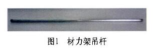
Such as lathe smooth rod, screw rod, suspender in material mechanics test-bed, etc. (the main product of this article), such parts are collectively called slender shaft. The slender shaft parts have poor rigidity and weak bending resistance. During the turning process, it is susceptible to bending deformation due to factors such as cutting force, gravity and cutting heat. Making the parts conical, waist drum shape, water wave pattern and slub grain and so on, not only causes the quality deterioration of the machining surface seriously, but also shortens the life of the machine tool and the tool.
1. Cause Analysis of Deformation in Slender Shaft Turning
In processing, the main reasons for the bending and bending of the slender shaft are:
(1) The cutting force causes deformation.
The cutting forces generated during turning can be broken down into: Axial cutting force, radial cutting force Fp and main cutting force Fzc. Different cutting forces have different effects on the bending deformation of the elongated shaft.
The influence of the axial cutting force Fp. The axial cutting force is a force acting in parallel on the axis of the elongated shaft. When the axial cutting force exceeds a certain value, the elongated shaft is bent. Therefore, the workpiece is longitudinally bent and deformed (the short-axis machining is generally negligible, and its influence on the bending deformation of the workpiece is not very large).
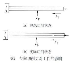
The effect of the radial cutting force FP (see Figure 2).
The radial cutting force acts vertically in a horizontal plane through the axis of the elongated shaft. Due to the poor rigidity of the elongated shaft, the radial force will bend the elongated shaft to cause bending deformation in the horizontal plane.
(2) The influence of cutting heat.
During turning, due to the influence of cutting heat, the workpiece gradually elongates and deforms with increasing temperature. This phenomenon is called thermal deformation.
The thermal elongation formula of workpiece length is as follows:
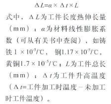
It can be seen from the above formula that the workpiece suspender will extend 0.267 mm during processing. In turning, the top of chuck and tailstock is fixed, so the distance between them is constant. Because the elongation of slender shaft is limited after being heated, the slender shaft is extruded to produce bending deformation. Therefore, in order to improve the processing accuracy of slender shaft, the stress and thermal deformation of the process system should be solved.
2. The Technological Method to Solve the Deformation of Slender Shaft in Turning Process
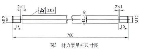
There is a suspender 760 mm long and 14 mm direct in the multi-functional test bed of product material mechanics (see Fig. 3). It is a typical elongated shaft part. In the initial processing process, due to the unreasonable processing technology, it is difficult for the workpieces of the vehicle to meet the requirements of the drawings, so that the parts have defects such as taper, water ripple and slubs (see Figure 4). Due to the unreasonable processing technology in the initial processing process, it is difficult to meet the requirements of the design of the turning workpiece, resulting in taper, water ripple and slub ripple (see Figure 4) defects of the parts. By improving the clamping method, adjusting the amount of cutting, changing the cutting process and other changes in the machining process, the qualified parts are finally processed.
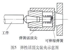
(1) Adopt one clip and one top method.
If you use a normal tip, it is affected by the heat of cutting. The workpiece will certainly be bended by the axial extrusion surface, so the elastic movable top (see Figure 5) is used to make the long axis stretch freely after being heated, so as to improve the processing accuracy. At the same time, an open steel ring of about 3--5 mm is inserted between the chuck jaw and the elongated shaft. Reduce the length of the axial contact between the claw and the slender shaft, eliminate the over-positioning during clamping, thereby reducing the bending deformation (see figure 6).
Heel rack with ball contact
In order to increase the rigidity and stability of workpiece, the auxiliary support of heel tool holder is used in production. Normal heel tool holder is supported by two claws, but because the downward gravity of the workpiece and the straightening of the workpiece are not ideal, turning instantaneously leaves the supporting claw, vibration occurs when contacting the supporting claw, and water ripple is easy to form. Finally, the three-claw heel cutter holder contacted by ball is chosen to restrict the movement of the workpiece from top to bottom and from left to right, so that it can only rotate around the axis. The turning vibration and the deformation of the workpiece are reduced, and the tool holder that contacts the balls changes the sliding friction into rolling friction, which reduces the frictional resistance.
Note when using the tool holder:
1. The spindle speed should not be too high, and the lubricating oil on the supporting claws should be prevented to prevent excessive wear.
2, The supporting force of each claw should be adjusted reasonably, too loose to support. Over-tightening affects the shape accuracy of the workpiece, and is prone to bamboo shape, which affects the processing quality.
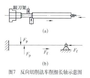
(2) Turning slender shaft by reverse cutting method
When cutting, the turning tool is fed from the chuck to the tailstock, which is called reverse cutting method (see Figure 7). At this time, the axial cutting force produced in the processing makes the slender bearing bear tension, eliminating the deformation caused by the axial cutting force.
In reverse cutting process, a transition shaft needs to be pre-processed, but it can not guarantee that it is coaxial with the processing axis, so it is decided not to use it.
(3) Double-cutter turning.
Double-knife turning (see Figure 8) is simultaneous turning with two front and rear turning tools. The two turning tools are diametrically opposed, the front knives are installed, and the rear knives are reverse mounted. When the turning, the radial cutting forces generated by the two knives cancel each other out, so the workpiece is subjected to force deformation and vibration, and the machining accuracy is good. However, it is necessary to modify the skateboard in the lathe and increase the rear tool holder, so the cost becomes high, and it is only suitable for professional mass production.

(4) Reasonable choice of cutting amount.
The choice of cutting speed (v). Figure 9 shows the selection of the cutting speed (v). Figure 9 shows the relationship curve.
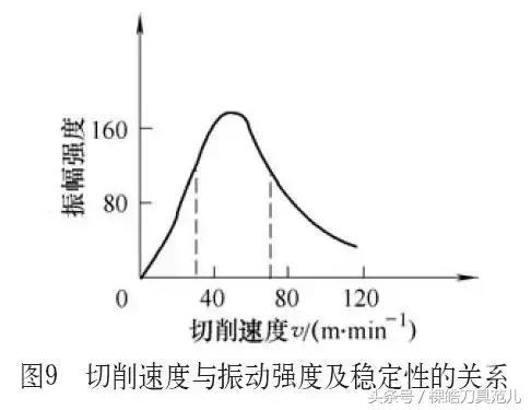 As can be seen from Figure 9. When turning, v-likely in the speed range of 30~70m/min, it is easy to generate vibration, and the corresponding amplitude value is larger at this time; Above or below this range, the vibration appears to decrease. Therefore, when the processing diameter is <15mm, take v<30m/min; When the processing diameter is >15 mm, v>70 m/min is taken.
Feed volume / selection.
Select a large feed amount when the machine power stiffness is 4. According to experience, when the rough car is taken at 0.15mm/r, when the semi-finished car is at /=0.1mm/r, the refined car is 0.06mm/r.
Selection of cutting depth.
As the depth of cut increases, the cutting force and cutting heat generated during turning increase, and the stress and deformation of the elongated shaft also increase. Therefore, the cutting depth should be minimized when machining slender shafts. According to experience, ap=1mm when roughing, ap=0.5mm for semi-finishing, and ap=0.25mm for finishing.
Front angle ro.
The size of the rake angle directly affects the cutting force and cutting temperature.
Increasing the rake angle reduces the cutting deformation of the metal layer being cut. It can be seen from the experiment that the current angle ro is increased by 10°, and the radial component force Fp can be reduced by 30%. The chip of the rake face is generally ro=15~30 degrees. The chip breaking groove on the rake face of the turning tool is 2~4 mm wide, which makes the chip flowing and the chip rolling performance good.
Leading angle Kr.
The lead angle increases, the radial cutting force decreases, and the lead angle Kr=75°~° (the cutter fashion is 85°~88°).
Edge inclination angle.
Affect the cutting flow direction during turning, the blade inclination angle increases, and the radial cutting force decreases, generally in the range of -10° to +10°. When the slender shaft is machined, it adopts +3°~+10° to make the cutting flow to the surface to be machined, thus protecting the machined surface.
(6) Machining of slender shaft threads.
Slender shaft threads (below M12) are difficult to process on machine tools. The usual method is to use plate teeth directly to cover them (see Figure 10).
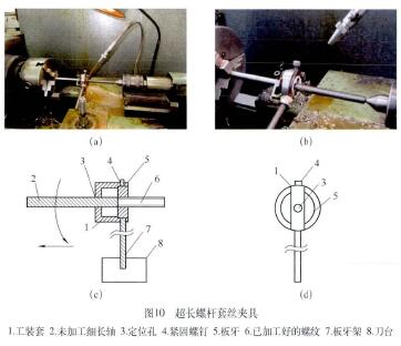
It is found that half-edge cutting is easy to occur when thread is set by common plate-tooth device, which results in tip damage, poor quality, low efficiency and high rejection rate. In order to make up for the shortcomings and improve the processing accuracy of slender shaft threads, the common plate tooth sleeve is refitted as shown in Figure 10.
The ultra-long screw ferrule fixture includes a tooling super long screw ferrule clamp. Including the round hole in front of the tooling to ensure the precision of the ultra-long screw machining (the hole is mainly used for guiding) and the cage for connecting the round hole. There is a fixed die sleeve on the back, and there are two threaded holes on the sleeve (one for connecting the support rod and the other for rotating the fastening screw to fix the die on the sleeve). When processing the ultra-long screw, the bar is clamped at one end and the other end is placed in the positioning hole (the bar diameter is smaller than the diameter of the hole by 0.05 - 0.15 mm), and the bar rotates. The ultra-long screw ferrule clamp is moved forward, and the bar material is processed by the inner dies of the ultra-long screw ferrule fixture, and the high-precision ultra-long screw can be processed.
(7) Turning method of the material frame hanger.
Through the above test analysis, it was decided to solve the problems in production by the following methods.
First, the machine tool was adjusted in two aspects:
1. The adjustment of the lathe spindle and the lathe spindle are too loose, which is easy to cause proper adjustment during turning, thus preventing the machine from jumping and swaying from adversely affecting the machining of the parts.
2. The adjustment of the tailstock, if the centerline of the tailstock and the centerline of the main shaft are not on a horizontal line, a coaxiality error occurs, and the workpiece out of the vehicle must be tapered.
Secondly, the processing technology of the parts is analyzed, and the processing technology is determined (see attached table).
After the above method, the problems in the production of the boom can be solved and the products can be qualified.
In machining, the ratio of length to diameter of many parts is 20-25 (1/D>20--25).
Such as lathe smooth rod, screw rod, suspender in material mechanics test-bed, etc. (the main product of this article), such parts are collectively called slender shaft. The slender shaft parts have poor rigidity and weak bending resistance. During the turning process, it is susceptible to bending deformation due to factors such as cutting force, gravity and cutting heat. Making the parts conical, waist drum shape, water wave pattern and slub grain and so on, not only causes the quality deterioration of the machining surface seriously, but also shortens the life of the machine tool and the tool.
1. Cause Analysis of Deformation in Slender Shaft Turning
In processing, the main reasons for the bending and bending of the slender shaft are:
(1) The cutting force causes deformation.
The cutting forces generated during turning can be broken down into: Axial cutting force, radial cutting force Fp and main cutting force Fzc. Different cutting forces have different effects on the bending deformation of the elongated shaft.
The influence of the axial cutting force Fp. The axial cutting force is a force acting in parallel on the axis of the elongated shaft. When the axial cutting force exceeds a certain value, the elongated shaft is bent. Therefore, the workpiece is longitudinally bent and deformed (the short-axis machining is generally negligible, and its influence on the bending deformation of the workpiece is not very large).
The effect of the radial cutting force FP (see Figure 2).
The radial cutting force acts vertically in a horizontal plane through the axis of the elongated shaft. Due to the poor rigidity of the elongated shaft, the radial force will bend the elongated shaft to cause bending deformation in the horizontal plane.
(2) The influence of cutting heat.
During turning, due to the influence of cutting heat, the workpiece gradually elongates and deforms with increasing temperature. This phenomenon is called thermal deformation.
The thermal elongation formula of workpiece length is as follows:
It can be seen from the above formula that the workpiece suspender will extend 0.267 mm during processing. In turning, the top of chuck and tailstock is fixed, so the distance between them is constant. Because the elongation of slender shaft is limited after being heated, the slender shaft is extruded to produce bending deformation. Therefore, in order to improve the processing accuracy of slender shaft, the stress and thermal deformation of the process system should be solved.
2. The Technological Method to Solve the Deformation of Slender Shaft in Turning Process
There is a suspender 760 mm long and 14 mm direct in the multi-functional test bed of product material mechanics (see Fig. 3). It is a typical elongated shaft part. In the initial processing process, due to the unreasonable processing technology, it is difficult for the workpieces of the vehicle to meet the requirements of the drawings, so that the parts have defects such as taper, water ripple and slubs (see Figure 4). Due to the unreasonable processing technology in the initial processing process, it is difficult to meet the requirements of the design of the turning workpiece, resulting in taper, water ripple and slub ripple (see Figure 4) defects of the parts. By improving the clamping method, adjusting the amount of cutting, changing the cutting process and other changes in the machining process, the qualified parts are finally processed.
(1) Adopt one clip and one top method.
If you use a normal tip, it is affected by the heat of cutting. The workpiece will certainly be bended by the axial extrusion surface, so the elastic movable top (see Figure 5) is used to make the long axis stretch freely after being heated, so as to improve the processing accuracy. At the same time, an open steel ring of about 3--5 mm is inserted between the chuck jaw and the elongated shaft. Reduce the length of the axial contact between the claw and the slender shaft, eliminate the over-positioning during clamping, thereby reducing the bending deformation (see figure 6).
Heel rack with ball contact
In order to increase the rigidity and stability of workpiece, the auxiliary support of heel tool holder is used in production. Normal heel tool holder is supported by two claws, but because the downward gravity of the workpiece and the straightening of the workpiece are not ideal, turning instantaneously leaves the supporting claw, vibration occurs when contacting the supporting claw, and water ripple is easy to form. Finally, the three-claw heel cutter holder contacted by ball is chosen to restrict the movement of the workpiece from top to bottom and from left to right, so that it can only rotate around the axis. The turning vibration and the deformation of the workpiece are reduced, and the tool holder that contacts the balls changes the sliding friction into rolling friction, which reduces the frictional resistance.
Note when using the tool holder:
1. The spindle speed should not be too high, and the lubricating oil on the supporting claws should be prevented to prevent excessive wear.
2, The supporting force of each claw should be adjusted reasonably, too loose to support. Over-tightening affects the shape accuracy of the workpiece, and is prone to bamboo shape, which affects the processing quality.
(2) Turning slender shaft by reverse cutting method
When cutting, the turning tool is fed from the chuck to the tailstock, which is called reverse cutting method (see Figure 7). At this time, the axial cutting force produced in the processing makes the slender bearing bear tension, eliminating the deformation caused by the axial cutting force.
In reverse cutting process, a transition shaft needs to be pre-processed, but it can not guarantee that it is coaxial with the processing axis, so it is decided not to use it.
(3) Double-cutter turning.
Double-knife turning (see Figure 8) is simultaneous turning with two front and rear turning tools. The two turning tools are diametrically opposed, the front knives are installed, and the rear knives are reverse mounted. When the turning, the radial cutting forces generated by the two knives cancel each other out, so the workpiece is subjected to force deformation and vibration, and the machining accuracy is good. However, it is necessary to modify the skateboard in the lathe and increase the rear tool holder, so the cost becomes high, and it is only suitable for professional mass production.
(4) Reasonable choice of cutting amount.
The choice of cutting speed (v). Figure 9 shows the selection of the cutting speed (v). Figure 9 shows the relationship curve.
Feed volume / selection.
Select a large feed amount when the machine power stiffness is 4. According to experience, when the rough car is taken at 0.15mm/r, when the semi-finished car is at /=0.1mm/r, the refined car is 0.06mm/r.
Selection of cutting depth.
As the depth of cut increases, the cutting force and cutting heat generated during turning increase, and the stress and deformation of the elongated shaft also increase. Therefore, the cutting depth should be minimized when machining slender shafts. According to experience, ap=1mm when roughing, ap=0.5mm for semi-finishing, and ap=0.25mm for finishing.
Front angle ro.
The size of the rake angle directly affects the cutting force and cutting temperature.
Increasing the rake angle reduces the cutting deformation of the metal layer being cut. It can be seen from the experiment that the current angle ro is increased by 10°, and the radial component force Fp can be reduced by 30%. The chip of the rake face is generally ro=15~30 degrees. The chip breaking groove on the rake face of the turning tool is 2~4 mm wide, which makes the chip flowing and the chip rolling performance good.
Leading angle Kr.
The lead angle increases, the radial cutting force decreases, and the lead angle Kr=75°~° (the cutter fashion is 85°~88°).
Edge inclination angle.
Affect the cutting flow direction during turning, the blade inclination angle increases, and the radial cutting force decreases, generally in the range of -10° to +10°. When the slender shaft is machined, it adopts +3°~+10° to make the cutting flow to the surface to be machined, thus protecting the machined surface.
(6) Machining of slender shaft threads.
Slender shaft threads (below M12) are difficult to process on machine tools. The usual method is to use plate teeth directly to cover them (see Figure 10).
It is found that half-edge cutting is easy to occur when thread is set by common plate-tooth device, which results in tip damage, poor quality, low efficiency and high rejection rate. In order to make up for the shortcomings and improve the processing accuracy of slender shaft threads, the common plate tooth sleeve is refitted as shown in Figure 10.
The ultra-long screw ferrule fixture includes a tooling super long screw ferrule clamp. Including the round hole in front of the tooling to ensure the precision of the ultra-long screw machining (the hole is mainly used for guiding) and the cage for connecting the round hole. There is a fixed die sleeve on the back, and there are two threaded holes on the sleeve (one for connecting the support rod and the other for rotating the fastening screw to fix the die on the sleeve). When processing the ultra-long screw, the bar is clamped at one end and the other end is placed in the positioning hole (the bar diameter is smaller than the diameter of the hole by 0.05 - 0.15 mm), and the bar rotates. The ultra-long screw ferrule clamp is moved forward, and the bar material is processed by the inner dies of the ultra-long screw ferrule fixture, and the high-precision ultra-long screw can be processed.
(7) Turning method of the material frame hanger.
Through the above test analysis, it was decided to solve the problems in production by the following methods.
First, the machine tool was adjusted in two aspects:
1. The adjustment of the lathe spindle and the lathe spindle are too loose, which is easy to cause proper adjustment during turning, thus preventing the machine from jumping and swaying from adversely affecting the machining of the parts.
2. The adjustment of the tailstock, if the centerline of the tailstock and the centerline of the main shaft are not on a horizontal line, a coaxiality error occurs, and the workpiece out of the vehicle must be tapered.
Secondly, the processing technology of the parts is analyzed, and the processing technology is determined (see attached table).
After the above method, the problems in the production of the boom can be solved and the products can be qualified.


