The cylinder block \ box parts dowel hole machining
The processing of the positioning pin holes of the cylinder parts such as the cylinder block and the cylinder head has always been a key process. The remarkable feature of the box parts is that the process is complicated, and the processing content is required. The parts need to be processed by multiple machine tools, multiple processes and repeated processing. Since the positioning pin hole is the main positioning reference of the processing machine tool, the machining accuracy of the box type part depends largely on the accuracy of the positioning pin hole, especially the positional accuracy of the positioning pin hole. It also affects the processing accuracy of other processes and the performance of the complete machine (such as automotive engines). Therefore, various manufacturers at home and abroad are working hard to improve the processing accuracy of the positioning pin hole and seek the best processing method. The machining position accuracy of the foreign positioning pin hole has been increased from the past ±0.03mm (also some ±0.05mm) to the current ±0.02~±0.025mm, and the individual is ±0.015mm. The positional accuracy of the current positioning pin hole in China has reached ±0.025~±0.03mm, which is slightly lower than that of foreign countries. With the development of the automobile industry, China's automobile industry will also enter the ranks of the world, and these values must reach the advanced level in foreign countries. Therefore, how to improve the processing precision of the positioning pin hole is of great significance.
I. Positioning pin hole processing method
At present, the processing methods of the two positioning pin holes of the box cavity parts adopt the drilling, reaming process or the drilling, expanding and reaming process of the template guiding sleeve. The tool works under the guidance of the guide sleeve, and the cutter and the guide sleeve move relative to each other, and there is a gap, and the positional accuracy which can generally be achieved is ±0.05 mm. The new guide sleeve guarantees a slightly higher accuracy, but it gradually decreases with the continuous wear of the guide sleeve. Generally, the positional accuracy of the two positioning pin holes can only be stably ensured to be between ±0.05 and ±0.08 mm. In order to improve the positional accuracy of this process, many engine manufacturers have adopted a variety of measures, which are roughly as follows:
1. Improve the precision of the drill template guide hole with a coordinate accuracy of ±0.005.
2. The guiding length of the extension guide sleeve is L/d>3~5, the matching precision of the guide sleeve is H6/g5, and the shape error is not more than 0.005.
3. Minimize the distance between the guide sleeve and the machining hole.
4. In order to ensure the positioning accuracy of the template, the over-positioning method (3 to 6 cylindrical pins) is used to fix the template.
By adopting these methods, the positional accuracy of the positioning pin hole can be relatively improved, but to ensure or improve the guiding precision of the drill template, the fixture needs to be disassembled and re-corrected periodically. The bottom hole of the template controls the fit clearance of the drill sleeve. First, by determining the gaps required for each guide bush to adapt to the machining accuracy of the process. The second is to select according to the actual production situation and the actual size of the reamer guiding part. Frequent maintenance of the fixture part caused a lot of disassembly, assembly, and adjustment work, which brought difficulties to maintenance and management.
The processing precision of the foreign positioning pin hole is ±0.02~±0.025mm, which is generally processed by CNC machine tool or machining center. Some manufacturers also use a machining method with a carbide guide sleeve. The guide hole of the guide sleeve is matched with the cutter, and the guide sleeve is close to the surface of the workpiece to improve the positional accuracy of the hole machining. But this way the tool wears out quickly. In short, these processing methods can ensure the positional accuracy of the positioning pin hole processing, but greatly increase the equipment investment.
II. Locating pin hole machining machine equipment
The designed cylinder head positioning pin hole processing machine adopts rigid drilling and new technology. A lot of experimental work was done before design, including the influence of tool cutting speed on the drilling offset, the influence of the tool feeding speed on the drilling offset, and the influence of the tool overhang degree l on the drilling offset. Experiments have shown that only the tool overhang l has an effect on the borehole offset, and other factors have little effect (can be ignored under normal conditions).
A rigid drilling test diagram is shown in Figure 1.
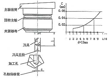
figure 1 Rigid drilling test chart
Note: 1. l is the tool overhang length
2. This experiment is tested on the coordinate sales
3. Reaming can further correct the offset during drilling
When the workpiece has a bottom hole in advance, precision boring (or rigid boring) can be used to machine a hole with high positional accuracy.
Such as: Boring holes in the coordinate boring pin.
When the workpiece has no bottom hole and the position accuracy of the drilling is required to be high, the center hole is usually punched before the drilling to ensure the hole position accuracy, but the machining accuracy is not as good as the former. In order to ensure that the machine has high hole machining accuracy and is suitable for mass production, the following measures are taken.
1. Short bit and short reamer are used to improve the rigidity of the tool system.
2. Four boring heads consisting of high-precision, high-rigidity single-axis boring heads (two for drilling and two for reaming). The shaft spacing can be adjusted (the shaft spacing can be adjusted to within ±0.005) to ensure the position of the hole with high precision and multi-variety processing.
3. Drilling and reaming with a high-rigidity double-station mobile workbench.
4. The use of guide sleeves in processing has the following advantages:
a. Use short drills and short reamer. When the processing part is close to the end of the spindle, the processing hole position is not easily offset, and the hole position accuracy is easily ensured.
b. There is no guide wear, it is easy to maintain stable machining accuracy for a long time, and the maintenance cost is greatly reduced.
I. Positioning pin hole processing method
At present, the processing methods of the two positioning pin holes of the box cavity parts adopt the drilling, reaming process or the drilling, expanding and reaming process of the template guiding sleeve. The tool works under the guidance of the guide sleeve, and the cutter and the guide sleeve move relative to each other, and there is a gap, and the positional accuracy which can generally be achieved is ±0.05 mm. The new guide sleeve guarantees a slightly higher accuracy, but it gradually decreases with the continuous wear of the guide sleeve. Generally, the positional accuracy of the two positioning pin holes can only be stably ensured to be between ±0.05 and ±0.08 mm. In order to improve the positional accuracy of this process, many engine manufacturers have adopted a variety of measures, which are roughly as follows:
1. Improve the precision of the drill template guide hole with a coordinate accuracy of ±0.005.
2. The guiding length of the extension guide sleeve is L/d>3~5, the matching precision of the guide sleeve is H6/g5, and the shape error is not more than 0.005.
3. Minimize the distance between the guide sleeve and the machining hole.
4. In order to ensure the positioning accuracy of the template, the over-positioning method (3 to 6 cylindrical pins) is used to fix the template.
By adopting these methods, the positional accuracy of the positioning pin hole can be relatively improved, but to ensure or improve the guiding precision of the drill template, the fixture needs to be disassembled and re-corrected periodically. The bottom hole of the template controls the fit clearance of the drill sleeve. First, by determining the gaps required for each guide bush to adapt to the machining accuracy of the process. The second is to select according to the actual production situation and the actual size of the reamer guiding part. Frequent maintenance of the fixture part caused a lot of disassembly, assembly, and adjustment work, which brought difficulties to maintenance and management.
The processing precision of the foreign positioning pin hole is ±0.02~±0.025mm, which is generally processed by CNC machine tool or machining center. Some manufacturers also use a machining method with a carbide guide sleeve. The guide hole of the guide sleeve is matched with the cutter, and the guide sleeve is close to the surface of the workpiece to improve the positional accuracy of the hole machining. But this way the tool wears out quickly. In short, these processing methods can ensure the positional accuracy of the positioning pin hole processing, but greatly increase the equipment investment.
II. Locating pin hole machining machine equipment
The designed cylinder head positioning pin hole processing machine adopts rigid drilling and new technology. A lot of experimental work was done before design, including the influence of tool cutting speed on the drilling offset, the influence of the tool feeding speed on the drilling offset, and the influence of the tool overhang degree l on the drilling offset. Experiments have shown that only the tool overhang l has an effect on the borehole offset, and other factors have little effect (can be ignored under normal conditions).
A rigid drilling test diagram is shown in Figure 1.
figure 1 Rigid drilling test chart
Note: 1. l is the tool overhang length
2. This experiment is tested on the coordinate sales
3. Reaming can further correct the offset during drilling
When the workpiece has a bottom hole in advance, precision boring (or rigid boring) can be used to machine a hole with high positional accuracy.
Such as: Boring holes in the coordinate boring pin.
When the workpiece has no bottom hole and the position accuracy of the drilling is required to be high, the center hole is usually punched before the drilling to ensure the hole position accuracy, but the machining accuracy is not as good as the former. In order to ensure that the machine has high hole machining accuracy and is suitable for mass production, the following measures are taken.
1. Short bit and short reamer are used to improve the rigidity of the tool system.
2. Four boring heads consisting of high-precision, high-rigidity single-axis boring heads (two for drilling and two for reaming). The shaft spacing can be adjusted (the shaft spacing can be adjusted to within ±0.005) to ensure the position of the hole with high precision and multi-variety processing.
3. Drilling and reaming with a high-rigidity double-station mobile workbench.
4. The use of guide sleeves in processing has the following advantages:
a. Use short drills and short reamer. When the processing part is close to the end of the spindle, the processing hole position is not easily offset, and the hole position accuracy is easily ensured.
b. There is no guide wear, it is easy to maintain stable machining accuracy for a long time, and the maintenance cost is greatly reduced.
c. The cutting speed of the tool can be increased by 1 to 2 times. When using high speed steel drill bit for rigid drilling, the cutting speed can reach more than 40m/min; When drilling with a carbide drill for rigid drilling, the cutting speed can reach more than 60m/min. Machine productivity is greatly improved.
5, the use of simple structure, good openness, easy to operate observation, smooth chip removal, easy maintenance of the fixture.
Due to the above measures, the position of the positioning pin hole processed by the machine tool is very high, reaching the world advanced level.
5, the use of simple structure, good openness, easy to operate observation, smooth chip removal, easy maintenance of the fixture.
Due to the above measures, the position of the positioning pin hole processed by the machine tool is very high, reaching the world advanced level.


