Several Blanking Processes Analysis
This regulation stipulates the operating rules and precautions that must be observed during the blanking process of the company.
This procedure applies to all blanking manufacturing processes of our company.
2. Reference standards
YB/JQ101.10 General technical condi
3 Process Specification Content
3.1 Preparation before processing (general)
3.1.1 Personnel preparation: The operator must hold a certificate, and the skill level is in line with the job requirements.
3.1.2 Security Preparation:
3.1.2.1 Wear labor protection articles as required: protective clothing, protective shoes, safety helmets, protective gloves, protective glasses, etc.; tie the cuffs, prohibit post-drinkers, and maintain a good mental state;
3.1.2.2 Check the braking performance of the transport equipment and check that the spreader meets the process requirements and their integrity.
3.1.3 Site preparation: Clean up the area within 2 meters of the equipment, worktables and operations. Place the required equipment for placing the parts in the storage area to ensure the flow of goods.
3.1.4 Equipment Preparation
3.1.4.1 Check whether the equipment is normal according to the TPM checklist of the equipment. If any abnormality is found, contact the equipment maintenance personnel to deal with it in time.
3.1.4.2 Before starting the equipment, it is necessary to carefully check whether the motor, switch, wiring and grounding are normal and firm, and check whether the operating parts and buttons of the equipment are in the correct position.
2. Cutting blanking
3.2.1 CNC plasma cutting machine blanking
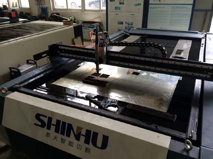
3.2.1.1 The first piece of inspection must be done to verify the accuracy of the cutting procedure, cutting template, and the cutting method; do a good job of sampling and final inspection.Avoid batch unqualified products and make inspection records;
3.2.1.2 Prior to cutting, the cutting parent metal should be placed flat and put, and the parent material must be fixed as required;
3.2.1.3 Select the torch according to the thickness of the board and who torch with the square, make sure the torch is perpendicular to the workpiece so that clean, vertical cuts are obtained;
3.2.1.4 set the torch process parameters according to the cutting board thickness, ignition test, make sure that the material is sprayed from the bottom of the workpiece and that it can be cut after passing inspection. CNC plasma cutting machine nozzle selection and cutting process parameters with reference to Table 1;
3.2.1.5 Before the formal cutting, it is necessary to put water first to ensure that the water level of the tank is 75-100mm higher than the cutting board surface;
3.2.1.6 Cut from the edge of the workpiece, unless it must be perforated, When perforating, the cutting torch is placed directly above the joint/cutting line of the workpiece to be perforated according to the discharging program;
3.2.1.7 During the cutting process, it is necessary to stick to the position and find abnormalities and stop the inspection in time;
3.2.1.8 After confirming that the cutting part has cooled down, it can directly contact the work piece by hand. In the absence of instructions, it is not allowed to cool the work piece by means of water-cooled, air-cooled and other rapid methods;
3.2.1.9 After cutting blanking, remove the slag and burr from the cutting edge;
3.2.1.10 After blanking, the workpiece needs to be placed neatly and marked accordingly to prevent loss and mixing.
3.2.1.11 After each shift, return the water in the tank to its original position and clean the slag on the working platform of the tank in time to keep the work surface clean.
Table 1 Numerical control plasma cutting machine nozzle and cutting process parameter selection table
|
Plasma gas flow rate |
Plasma gas pressure |
Protective gas flow rate |
Protective gas pressure |
Material thickness |
Cutting torch distance from the workpiece |
Arc voltage setting |
Walking speed |
About sports delay time
|
Nozzle aperture |
|
|
test |
Running |
bar |
mm |
mm |
Volts |
mm/min |
sec |
φ/ mm |
||
|
31 |
3.0~3.3 |
4.0~4.3 |
132 |
4.8 |
6 |
3 |
130 |
3300 |
0.5 |
4 |
|
8 |
3 |
135 |
2700 |
0.5 |
||||||
|
10 |
3 |
135 |
2400 |
1.0 |
||||||
|
12 |
3 |
140 |
1900 |
2.0 |
||||||
|
15 |
4 |
145 |
1200 |
2.0 |
||||||
|
20 |
5 |
150 |
850 |
2.5 |
||||||
|
25 |
6 |
165 |
400 |
3.0 |
5 |
|||||
3.2.2 CNC flame cutting machine blanking
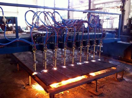
3.2.2.1 The first piece of inspection must be done to verify the accuracy of the cutting procedure, cutting template, and the cutting method; do a good job of sampling and final inspection. Avoid batch unqualified products and make inspection records;
3.2.2.2 Our company's CNC flame cutting machine uses oxygen-propane cutting. When using oxygen-propane cutting, note the following:
3.2.2.2.1 Propane cylinders must be placed in a well-ventilated area. Do not place them in basements, semi-basements, or poorly ventilated areas. Prevent gas from leaking in low-lying areas and cause fire.
3.2.2.2.2 When the propane gas cylinder is about to run out, there is residual gas in the cylinder to facilitate checking the gas sample before filling and preventing other gases from entering the bottle;
3.2.2.2.3 When the cylinder is on fire, the bottle valve should be closed immediately. If it cannot be approached, a large amount of cold water can be injected to cool the bottle body, and then the bottle valve is closed to cut off the gas source to extinguish the fire while preventing the bottle body from falling on fire. When it is not possible to stop the leakage of the cylinder valve, the bottle body should be moved to an outdoor safety zone so that the gas escapes until the gas in the bottle is exhausted.
3.2.2.3 Prior to cutting, the cutting parent metal should be placed flat and the parent material must be fixed as required.
3.2.2.4 Select the cutting nozzle according to the thickness of the plate. Before the cutting nozzle is used, it is necessary to check whether the taper surface is damaged to prevent air leakage. If the cut-off hole is blocked due to trash or debris, use a needle or wire brush to brush the hole;
3.2.2.5 Set the cutting process parameters according to the cutting board thickness. Only after passing the ignition test can the cutting be performed. CNC torch cutting torch selection and cutting process parameters with reference to Table 2; (If the requirements in the instruction manual for the propane series nozzle used are different from the reference data in Table 2, the requirements in the instruction manual shall prevail.)
Table 2 CNC Flame Cutting Machine Oxygen-Propane Constant Pressure Torch and Cutting Process Parameter Selection Table
|
Cutting nozzle No. |
Cutting thickness (mm) |
Oxygen pressure (Mpa) |
Propane gas pressure (Mpa) |
Cutting speed (mm/min) |
Note |
|
1 |
5~10 |
0.3 |
0.03 |
500~450 |
Machine with equal pressure cutting torch |
|
2 |
10~20 |
0.3 |
0.03 |
450~350 |
|
|
3 |
20~40 |
0.35 |
0.03 |
350~300 |
|
|
4 |
40~60 |
0.45 |
0.04 |
300~250 |
|
|
5 |
60~100 |
0.6 |
0.04 |
250~230 |
|
|
6 |
100~150 |
0.7 |
0.04 |
230~200 |
|
|
7 |
150~180 |
0.8 |
0.05 |
200~170 |
|
|
8 |
180~220 |
0.9 |
0.05 |
170~140 |
|
|
9 |
220~260 |
0.95 |
0.05 |
140~90 |
|
|
10 |
260~300 |
1.0 |
0.05 |
90~70 |
3.2.3 gas cutting hand-cutting blanking
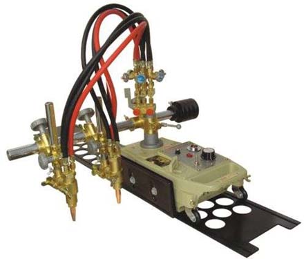
3.2.3.1 The first piece of inspection must be done to verify the accuracy of the cutting procedure, cutting template, and the cutting method; do a good job of sampling and final inspection. Avoid batch unqualified products and make inspection records;
3.2.3.2 Use oxygen-acetylene cutting. Before cutting, attach the torch to the fixed hose connector. Check whether the oxygen meter and the acetylene safety pot are working properly and whether the torch shooting force is good;
3.2.3.3 When using an oxygen cylinder, the oxygen cylinder should be put steady, and the dust at the interface should be cleaned, and then the oxygen gauge should be installed. When the pressure in the bottle is lower than the working pressure, it must be replaced, and the mobile gas cylinder should avoid impact and it is forbidden to dip oil;
3.2.3.4 When using the acetylene generator, the acetylene generator must be 10 meters away from the source, 3 meters away from the oxygen cylinder, and 1 meter away from the heating equipment, and must not be placed on the sidewalk or under the high-pressure line;
3.2.3.5 Keep enough clean water in the acetylene generator to maintain a certain water level in the water seal and flashback preventer;
3.2.3.6 The amount of calcium carbide added in the acetylene generator should be stipulated once and the degree of calcium carbide should meet the requirements, generally 50-80mm.
3.2.3.7 Check the workpiece against the drawing. The unevenness of the gas cutting steel plate should be in accordance with the provisions, generally the plate thickness is less than 14 mm, the unevenness of the steel plate is 2/1000, and the unevenness of the steel plate larger than 14 mm is 1/1000 (the process card requires the process card to prevail);
3.2.3.8 manage the site, flatten the workpiece, and leave a gap of not less than 100 mm below the plate, and remove rust, oil, etc. in the range of 30-50 mm on both sides of the slicing of the workpiece;
3.2.3.9 Select the cutting torch according to the thickness of the steel plate, and adjust the cutting process parameters in accordance with the provisions, refer to Table 3;
table 3 Oxygen-propane injection torch and cutting process parameter selection table
| Cutting nozzle model | Cutting thickness (mm) | Oxygen pressure ((Mpa) | Propane gas pressure (Mpa) | Note |
|
1* 2* 3* |
5~10 10~20 20~30 |
0.2 0.25 0.3 |
0.03 | With G01-30 cutting torch |
|
1 2 3 4 5 |
5~10 10~20 20~40 40~60 60~100 |
0.2 0.25 0.3 0.4 0.5 |
0.03 0.03 0.03 0.04 0.04 |
With G01-100 cutting torch |
|
7 8 9 10 |
100~150 150~180 180~220 220~260 260~300 |
0.6 0.7 0.8 0.9 1.0 |
0.04 0.04 0.05 0.05 0.05 |
With G01-300 cutting torch |
3.2.4 Profiling cutting machine cutting blanking
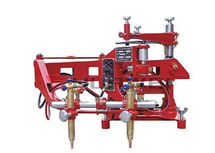
3.2.4 Profiling cutting machine cutting blanking
3.2.4.2 Sample Making
3.2.4.2.1 The sample material is made of low-carbon steel plate, the thickness requirement is greater than 4mm, and the thickness of large sample plate is 6mm, so as to achieve sufficient magnetic adsorption force. The sample plate is made by the workshop according to the shape and size requirements of the parts;
3.2.4.2.2 model manufacturing size calculation: Because the magnetic roller and the cutting nozzle centerline are installed on the same vertical axis, the magnetic roller moves against the template to drive the cutting torch to form a similar workpiece. So the template size does not equal the required working size. It has a certain relationship with the radius of the magnetic roller and the kerf radius of the selected cutting nozzle. The formula is as follows:
1 Sample size radius of the workpiece of the outer wrapping line = radius of the workpiece size - (radius of magnetic roller - radius of kerf)
2 Model size radius of the inner envelope workpiece = workpiece size radius + (magnetic roller radius - slitting radius) Magnetic roller diameter = φ10mm
Cutting torch number 1 2 3
Slot width 2mm 2.6mm 3.2mm
Note: The tip width is for reference only
3.2.4.2.3 Cutting operation: Our factory profile cutting machine is equipped with four valves: acetylene valve, preheating oxygen valve, cutting valve and automatic control valve.
The operation is as follows:
1, Open the automatic control valve → Open the acetylene valve 1/4 to 1/2 turn → Ignite → Open the preheating oxygen valve to adjust the flame, preheat the steel plate → Open the cutting oxygen valve → Start cutting (if the flame change needs to be readjusted) → Need to adjust the speed of movement;
2, Cutting is completed → Close the cutting oxygen valve → Close the acetylene valve → Close the preheating oxygen valve → Turn off the power and stop.
3.2.4.3 Remove slag and burrs after the part has been cut.
Table 4 copying cutting machine cutting nozzle specifications
| Cutting nozzle model | Cutting oxygen aperture (mm) | Cutting thickness (mm) | Cutting speed (mm/min) | Gas pressure (Mpa) | Gas consumption (reference) | ||
| Oxygen | acetylene | Oxygen (M/h) | acetylene(L/h) | ||||
| 00 | 0.8 | 5~10 | 600~450 | 0.2~0.3 | ≥0.03 | 0.9~1.3 | 340 |
| 0 | 1.0 | 10~20 | 480~380 | 1.3~1.8 | 340 | ||
| 1 | 1.2 | 20~30 | 400~320 | 0.25~0.35 | 2.5~3.0 | 470 | |
| 2 | 1.4 | 30~50 | 350~280 | 3.0~4.0 | 470 | ||
| 3 | 1.6 | 50~70 | 300~240 | 0.3~0.4 | ≥0.04 | 4.5~6.0 | 620 |
| 4 | 1.8 | 70~90 | 260~200 | 5.5~7.0 | 620 | ||
| 5 | 2.0 | 90~120 | 210~170 | 0.4~0.5 | 8.5~10.5 | 620 | |
|
Data cutting conditions in the table: 1. The purity of oxygen is not lower than 99.5%; 2. The carbon content of the cut steel is ≤ 0.45%; 3, the cutting method is vertical cutting; 4. Oxygen pressure refers to cutting oxygen pressure before cutting torch |
|||||||
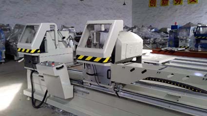
3.3 sawing blanking
3.3.1 Check whether the oil reservoir in the machine bed has been filled with enough hydraulic oil (oil performance is not less than 30# ordinary hydraulic oil);
3.3.2 Check if sufficient high-performance coolant has been injected into the coolant tank, but do not exceed the middle of the coolant tank oil standard and check that the ejected coolant is smooth;
3.3.3 Adjust the pressure of the hydraulic system. Under normal circumstances, the oil pressure reaches 1.4Mpa is enough (Our company's existing GB4040/60H band sawing machine's hydraulic pressure must not exceed 2.5Mpa);
3.3.4 According to the material of the workpiece material to be sawed, select the number of teeth, the feed rate, and the linear velocity of the saw blade.
Under normal circumstances, the line speed of the band saw blade should not be higher than 59m/min. For harder materials, the speed should be adjusted accordingly. See Table 5; (Our company's existing GB4040/60H band sawing machine with standard band saw size 4800 × 34 × 1.1mm)
3.3.5 Install the saw blade. Do not install the blade. The teeth (cutting edges) of the saw blade must face the rear wheel box.Use a torque wrench to check the tension of the saw blade. First loosen the tensioned saw blade a little, then use a torque wrench (torque adjusted to 25N.m) to tension the saw blade at the top of the front wheel box (above the screw lever handle). When tension is heard, the sound wrench “grid” “grid” “grid” sound indicates that the saw blade has been tensioned to an appropriate degree;
3.3.7 Check whether the stop button is sensitive and absolutely reliable;
3.3.8 Make the saw blade fall to the lowest position, then rise to the highest position, make 2 to 3 empty return trips, observe whether the sound is safe and normal when the machine tool is idle;
3.3.9 Adjust the left guide arm position according to the width (or diameter) of the workpiece. The distance between the left and right guide arm is only slightly larger than the size of the workpiece to be saw.
3.3.10 Adjust the width of the clamping vise according to the width of the workpiece. Under normal circumstances as long as slightly larger than the workpiece material to be saw between 10 ~ 25mm;
3.3.11 Feeding, adjust and fix the fixed-length baffle according to the process requirements, and clamp the material with a vise. During the sawing process, the base material must depend on the solid baffle. We must conscientiously make the first inspection to verify that the length is accurate; do a random inspection of the process to prevent the production of batches of nonconforming products; final inspections, and inspection records
3.3.12 When the machine tool is abnormal in the sawing process, the operator should immediately press the stop button SB1;
3.3.13 Sawdust in the rear wheel box should be removed frequently during sawing. If the sawdust rolls between the saw blade and the reel, the saw blade breaks easily;
table 5 Feed rate, line speed selection reference table
| Materials | Tensile strength (kg force/mm) | Hardness HB | Number of gears 25 | Gear shape | Line speed (m/min) | Feed speed (cm2/min) | Representative material |
| Free cutting material | <40 | <120 | 4 | H | 78 | 65 | General non-ferrous metal materials |
| 40~50 | <180 | 4 | H | 78 | 60 | Annealed 15Cr steel, Y12 steel | |
| 45~58 | 150~180 | 4 | R | 59 | 55 | Normalizing 30 steel, low carbon steel | |
| Common material | 60~70 | 180~240 | 4,4~6 | R | 59 | 50 | 45 steel, gray cast steel |
| 75~90 | 250~275 | 4,4~6 | R | 39 | 35 | 2Cr13 quenched and tempered steel, hot rolled steel 85 | |
| Hard cutting material | 95~110 | 260~300 | 4,4~6 | R | 26 | 25 | Conditioning 45Cr steel, 65Mn steel, stainless steel, bearing steel |
| >120 | 300 | 4,4~6 | R | 26 | 20 |
|
Sawing length Round steel diameter |
≤50 | 50~200 | 200~500 | 500~1000 | >1000 | Sawing |
| >50~80 |
+0.5 0 |
+0.5 0 |
+2.0 0 |
+2.0 0 |
+2.5 0 |
3 |
| >80~100 |
+0.5 0 |
+2.0 0 |
+2.0 0 |
+2.5 0 |
+2.5 0 |
7 |
| >100~120 |
+0.5 0 |
+2.0 0 |
+2.0 0 |
+2.5 0 |
+2.5 0 |
7 |
| >120~180 |
+2.0 0 |
+2.0 0 |
+2.5 0 |
+2.5 0 |
+3.0 0 |
8 |